Thoroughly analyzing AP Inter 2nd Year Physics Model Papers Set 2 helps students identify their strengths and weaknesses.
AP Inter 2nd Year Physics Model Paper Set 2 with Solutions
Time: 3 Hours
Maximum Marks: 60
Section – A
Answer all questions. Each carries two marks. (10 × 2 = 20 Marks)
Question 1.
Define power of a cbnvex lens. What is its unit ?
Answer:
Power of a lens : Power of a lens is defined as its bending ability . and is measured as reciprocal of focal length in metre.
∴ Power of a lens (P) = \(\frac{1}{\mathrm{f} \text { (in metres) }}\) = \(\frac{100}{f(i n c m s)}\)
Unit → Dioptre (D)
Question 2.
What is Malus law.
Answer:
Malus’ law: It states that the intensity of polarised light transmitted through the analyser varies as a square of cosine of the angle between the plane of transmission of analyser and polariser.
I ∝ cos2 θ; I = I0 cos2 θ.
Question 3.
Write the expression for electric intensity due to an infinite long charged wire at a distance radial distance ‘r’ from the wire.
Answer:
The electric intensity due to an infinitely long charged wire
E = \(\frac{\lambda}{2 \pi \varepsilon \theta^r}\) perpendicular to the conductor.
Where λ = Uniform linear charge density
r = Distance of the point from the conductor.
![]()
Question 4.
What are meant by equipotential surfaces ?
Answer:
No work is doiie in moving a charge from one point on equipotential – surface to the other. Therefore, component of electric field intensity along the equipotential surface is zero. Hence, the surface is perpendicular to the field lines.
Question 5.
Define temperature coefficient of resistances.
Answer:
Temperature coefficient of resistivity (α): The ratio of the change in resistivity per 1°C rise in temperature to the resistivity at 0°C is called the temperature coefficient of resistivity.
α = \(\frac{\rho_{\mathrm{t}}-\rho_0}{\rho_0 t}\)
Question 6.
Distinguish between ammeter and voltmeter.
Answer:
| Ammeter | Voltmeter |
| 1) It is used to measure current. | 1) It is used to measure P. D between two points. |
| 2) Resistance of an ideal Ammeter is zero. | 2) Resistance of ideal voltmeter is infinity. |
| 3) It is connected in the circuits. | 3) It is connected in parallel series in the circuits. |
Question 7.
The force between two magnetic poles seperated by a distanced in air is F. At what distance between them does the force become doubled ?
Answer:
Force between two magnetic poles, F1 = F; .
Distance between two magnetic poles, d1 = d
Force between two magnetic poles increased by double F2 = 2F
Distance between two magnetic poles, d2 = ?
From Coulombs law, F1d12 = F2d22
Fd2 = 2 \(\mathrm{Fd}_2^2 \Rightarrow \mathrm{d}_2^2=\frac{\mathrm{d}^2}{2}\)
∴ d2 = \(\frac{d}{\sqrt{2}}\)
Question 8.
State Faraday’s law of electromagnetic induction.
Answer:
“Magnitude of induced e.m.f is directly proportional to the rate of change of magnetic flux”
ε ∝ \(\frac{\mathrm{d} \phi}{\mathrm{dt}}\)
Question 9.
How is impact parameter related to angle of scattering ?
Answer:
The impact parameter related to angle of scatting is given by
b = \(\frac{1}{4 \pi \varepsilon_0} \times \frac{\mathrm{Ze}^2}{\left(\frac{1}{2} m v^2\right)}\) cot θ2
![]()
Question 10.
What are thermal neutrons ? What is the importance ?
Answer:
Neutrons having kinetic energies approximately 0.025 eV are called as slow neutrons or thermal neutrons. 235U undergoes fission only when bombarded with thermal neutrons.
Section – B
Answer any six questions. Each carries four marks. (6 × 4 = 24 Marks)
Question 11.
Define critical angle. Explain total internal reflection using a neat diagram.
Answer:
Critical angle : When light ray travelling from denser medium to rarer medium, then the angie of incidence for which angle of refraction in air is 90° is called critical angle.
C = sin-1(\(\))
Total internal reflection : When a light ray travels from denser to rarer medium, the angle of incidence is greater than the critical angle, then it reflects into the same medium is called total internal reflection.
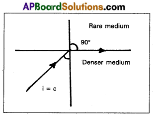
Explanation : Consider an object in the denser medium. A ray OA incident on XY bends away from the normal. As the angle of incidence is increased, the angle of refraction goes on increasing. For certain angle of incidence, the refracted ray parallel to XY surface (r = 90°)
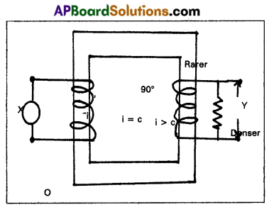
When the angle of incidence is further increased, the ray is not refracted but is totally reflected back in the denser medium. This phenomenon is called total internal reflection.
Question 12.
State Gauss’s law in electrostatics and explain its importance.
Answer:
Gauss’s law: The total electric flux through any closed surface is equal to \(\frac{1}{\varepsilon_0}\) times the net charge enclosed by the surface.
Total electric flux Φ = \(\oint_S \vec{E} \cdot d \vec{s}=\frac{q}{\varepsilon_0}\)
Here q is the total charge enclosed by the surface ‘S’, \(\oint\) represents
surface integral of the closed surface.
Importance:
- Gauss’s law is very useful in calculating the electric field in case of problems where it is possible to construct a closed surface. Such surface is called Gaussian surface.
- Gauss’s law is true for any closed surface, no matter what its shape or size.
- Symmetric considerations in many problems make the appli-cation of Gauss’s law much easier. ’
Question 13.
Derive an expression for the equivalent capacity when capacitors are connected in series.
Answer:
Series combination : If a number of condensers are connected end to end between the fixed points then such combination in called series.
In this combination
- Charge on each capacitor is equal.
- P.D’s across the capacitors is not equal.
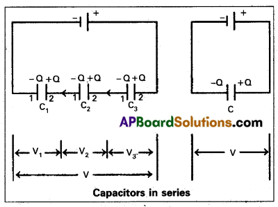
Consider three capacitors of capaci-tances C1, C2 and C3 are conne-cted in series across a battery of P.D ‘V’ as shown in figure.
Let ‘Q’ be the charge on each capacitor.
Let V1, V2 and V3 be the P.D’s of three capacitors then
V = V1 + V2 + V3 ……… (1)
P.D across Ist condenser V1 = \(\frac{\mathrm{Q}}{\mathrm{C}_1}\)
P.D across IInd condenser V2 = \(\frac{\mathrm{Q}}{\mathrm{C}_2}\)
P.D across IIIrd condenser V3 = \(\frac{\mathrm{Q}}{\mathrm{C}_3}\)
∴ From the equation (1) V = V1 + V2 + V3
= \(\frac{\mathrm{Q}}{\mathrm{C}_1}+\frac{\mathrm{Q}}{\mathrm{C}_2}+\frac{\mathrm{Q}}{\mathrm{C}_3}\) = Q[latex]\frac{1}{C_1}+\frac{1}{C_2}+\frac{1}{C_3}[/latex]
\(\frac{\mathrm{V}}{\mathrm{Q}}=\frac{1}{\mathrm{C}_1}+\frac{1}{\mathrm{C}_2}+\frac{1}{\mathrm{C}_3}\) [∵ \(\frac{1}{C}=\frac{V}{Q}\)]
For ‘n’ number of capacitors, the effective capacitance can be written as
\(\frac{1}{\mathrm{C}}=\frac{1}{\mathrm{C}_1}+\frac{1}{\mathrm{C}_2}+\frac{1}{\mathrm{C}_3}+\ldots \ldots+\frac{1}{\mathrm{C}_{\mathrm{n}}}\)
![]()
Question 14.
State the working principle of potentiometer explain with the help of ciruit diagram how the potentiometer is used to determine the interval resistance of the given primary cell.
Answer:
Working principle of potentiometer : The potential difference across a length of the potentiometer wire is directly proportional to its length (or) when a steady current is passed through a uniform wire, potential drop per unit length or potential gradient is constant,
i.e. ε ∝ l ⇒ ε = Φl
where Φ is potential gradient.
Measurement of internal resistance (r) with potentiometer:
1) Potentiometer to measure internal resistance (r) of a cell (ε) is shown in diagram.
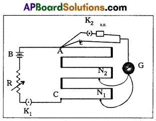
2) The cell (emf ε) whose internal resistance (r) is to be determined is connected across a resistance box (R.B) through a key K2.
3) With key K2 open, balance is obtained at length l1 (AN1).
Then ε = Φ l1 → (1)
4) When key K2 is closed, the cell sends a current (I) through the resitance box (R/B).
5) If V is the terminal potential difference of the cell and balance is obtained at length l2 (A2).
Then V = Φ l2 → (2)
6) \(\frac{(1)}{(2)} \Rightarrow \frac{\varepsilon}{\mathrm{V}}=\frac{l_1}{l_2}\) → (3)
7) But ε = I (r + R) and V = IR. This gives
\(\frac{\varepsilon}{V}=\frac{(r+R)}{R}\)
\(\frac{l_1}{l_2}\) = (\(\frac{r}{R}\) + 1) [∵ from (3)]
∴ r = R(\(\frac{l_1}{l_2}\) – 1)
Question 15.
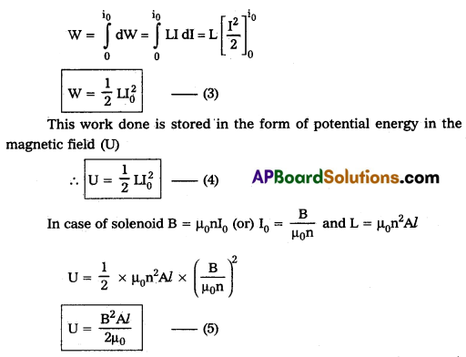
Obtain an expression for the magnetic energy stored in a solenoid in terms of the magnetic fieed, area and length of thfe solenoid.
Answer:
When the current flows through the inductor of inductance L, an e.m.f is induced in it is given by
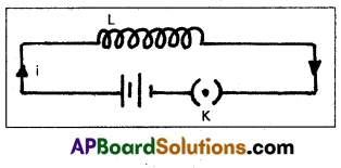
ε = – L\(\frac{\mathrm{dI}}{\mathrm{dt}}\) ……….. (1)
(-ve sign shows that e.m.f opposes the passage of current)
Let an infinitesmal charge dq be driven through the inductor. So; the work done by the external voltage is given by
dW = εdq (∵ v = \(\frac{\mathrm{dW}}{\mathrm{dq}}\))
dW = L\(\frac{\mathrm{dI}}{\mathrm{dt}}\) × dq (∵ I = \(\frac{\mathrm{dq}}{\mathrm{dt}}\))
dW = LI dI ……… (2)
Total work done to maintain the maximum current (I0) is given by
Question 16.
State the principle on which a transformer works. Describe the working of a transformer with necessary theory.
Answer:
Transformer is a device to convert a low alternating current of high voltage into high alternating current of low voltage and vice versa.
Principle : It works on the principle of mutual induction between two coils.
Working : When an alternating emf is applied across the primary coil, the input voltage changes with time. Hence the magnetic flux through the primary also changes with time.
This changing magnetic flux will be linked with secondary through the core. An emf is induced in the secondary.
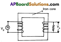
Theory : Let N1 and N2 be the number of turns in the primary and secondary. Let VP and VS be the emfs across the primary and secondary.
\(\frac{\mathrm{V}_{\mathrm{S}}}{\mathrm{V}_{\mathrm{P}}}=\frac{\text { Outputemf }}{\text { Input emf }}=\frac{-\mathrm{N}_2 \frac{\mathrm{d} \phi}{\mathrm{dt}}}{-\mathrm{N}_1 \frac{\mathrm{d} \phi}{\mathrm{dt}}}=\frac{\mathrm{N}_2}{\mathrm{~N}_1}\)
∴ \(\frac{V_S}{V_P}=\frac{N_2}{N_1}\) Transformer ratio.
Efficiency of transformer:
It is the ratio of output power to the input power.
η = \(\frac{\text { Output power }}{\text { Input power }}\) × 100
Question 17.
What are the limitations of Bohr’s theory of hydrogen atom ?
Answer:
Limitations of Bohr’s theory of Hydrogen atom :
- This theory is applicable only to simplest atom like hydrogen, with z = 1. The theory fails in case of atoms of other elements for which z > 1.
- The theory does not explain why orbits of electrons are taken as circular, while .elliptlical orbits are also possible.
- Bohr’s theory does not say anything about the relative intensities of spectral lines.
- Bohr’s theory does not take into account the wave properties of electrons.
![]()
Question 18.
Distinguish between nuclear fission and nuclear fusion.
Answer:
| Nuclear fission | Nuclear fusion |
| 1. In this process heavy nucleus is divided into two fragments along with few neutrons. | 1. In this process lighter nuclei will join together to produce heavy nucleus. |
| 2. These reactions will takes place even at room temperature. | 2. These reactions will takes place at veiy high tempera-ture such as 10<sup>6</sup> °C. |
| 3. To start fission atleast one thermal neutron from out side is compulsory. | 3. No necessary of external neutrons. |
| 4. Energy released per unit mass of participants is less. | 4. Energy released per unit mass of participants is high. Nearly seven time more than fission reaction. |
| 5. In this process neutrons are liberated. | 5. In this process positrons are liberated. |
| 6. This reaction can be controlled. Ex : Nuclear reactor. | 6. There is no control on fusion reaction. |
| 7. Atom bomb works on principle of fission reaction. | 7. Hydrogen bomb works on the principle of fusion reaction. |
| 8. The energy released in fission can be used for peaceful purpose. Ex : Nuclear reactor and Atomic power stations. | 8. The energy released in fusion cannot be used for peaceful purpose. |
Section – C
Answer any two of the following. Each carries 8 marks. (2 × 8 = 16 Marks)
Question 19.
Explain the formation of stationary waves in stretched strings and hence deduce the laws of transverse wave in stretched strings. A closed organ pipe 70 cm long is sounded. If the velocity of sound is 331 m/s, what is the fundamental frequency of vibration of the air column ?
Answer:
A string is a metal wire whose length is large when compared to its thickness. A stretched string is fixed at both ends, when it is plucked at mid point, two reflected waves of same amplitude and frequency at the ends are travelling in opposite direction and overlap along the length. Then the resultant waves are known as the standing waves (or) stationary waves.
Let two transverse progressive waves of same amplitude a, wave length λ and frequency ‘v’, travelling in opposite direction be given by
y1 = a sin (kx – ωt) and y2 = – a sin (kx + ωt)
where ω = 2πv and k = \(\frac{2 \pi}{\lambda}\)
The resultant wave is given by y = y1 + y2
y = a sin (kx – ωt) – a sin (kx + ωt)
y = (2a sin kx) cos ωt
2a sin kx = Amplitude of resultant wave.
It depend on ‘kx’ If x = 0, \(\frac{\lambda}{2}\), \(\frac{2 \lambda}{2}\), \(\frac{3 \lambda}{2}\) …. etc, the amplitude = zero
These positions are known as “Nodes”
If x = \(\frac{\lambda}{4}\), \(\frac{3 \lambda}{4}\), \(\frac{5 \lambda}{2}\) …… etc, the amplitude = maximum (2a).
These positions are called “Antinodes”
Formation of stationary waves : A stretched string can be vibrate in different frequencies and form stationary wave. This mode of vibrations are known as Harmonics.
If it vibrates in one segment, which known as ‘Fundamental Harmonic’. The Higher Harmonics are called the overtones.
It vibrates in two segments then the second Harmonic is called first overtone. Similarly the patterns of vibrations are as shown in figure.
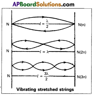
If the string vibrates in ‘P’ segments and ‘l’ is its length then length of each segment = \(\frac{l}{\mathrm{p}}\)
Which is equal to \(\frac{\lambda}{2}\)
∴ \(\frac{l}{\mathrm{p}}\) = \(\frac{\lambda}{2}\) ∴ ⇒ λ = \(\frac{2 l}{\mathrm{p}}\)
Harmonic frequency v = \(\frac{\mathrm{v}}{\lambda}=\frac{\mathrm{vp}}{2 l}\)
v = \(\frac{\mathrm{vp}}{2 l}\) ………. (1)
If ‘T’ is tension (stretching force) in the string and ‘µ’ is linear density then velocity of transverse wave (v) in the string is
v = \(\sqrt{\frac{T}{\mu}}\) ………. (2)
From the Eqs (1) and (2)
Harmonic frequency v = \(\frac{\mathrm{p}}{2 l} \sqrt{\frac{\mathrm{T}}{\mu}}\)
If p = 1 then it is called fundamental frequency (or) first harmonic frequency
∴ Fundamental Frequency v = \(\frac{1}{2 l} \sqrt{\frac{\mathrm{T}}{\mu}}\) ………… (3)
If p = 2 then it is first overtone (or) second harmonic frequency.
v1 = \(\frac{2}{2 l} \sqrt{\frac{\mathrm{T}}{\mu}}\) = 2v …………. (4)
Similarly if p = 3 then second overtone (or) third harmonic frequency.
v2 = \(\frac{3}{2 l} \sqrt{\frac{\mathrm{T}}{\mu}}\) = 2v …………. (5)
from the Eqs (3), (4) and (5)
The ratio of the frequencies of harmonics are
v : v1 : v2 = v : 2v : 3v = 1 : 2 : 3
∴ The frequencies of the overtones in a given vibrating length, are integral multiples of the fundamental in the same length.
Laws of Transverse Waves Along Stretched String :
Fundamental frequency of the vibrating string v = \(\frac{1}{2 l} \sqrt{\frac{\mathrm{T}}{\mu}}\)
First Law: When the tension (T) and linear density (µ) are constant, the fundamental frequency (v) of a vibrating string is inversely proportional to its length.
∴ v ∝ \(\frac{1}{l}\) ⇒ vl = constant, when ‘T’ and ‘µ’ are constant.
Second Law : When the length (l) and its, linear density (m) are constant the fundamental frequency of a vibrating string is directly proportional to the square root of the stretching force (T).
∴ v ∝ √T ⇒ \(\frac{v}{\sqrt{T}}\) = constant, when T ‘l’ and ‘m’ are constant.
Third Law : When the length (l) and the tension (T) are constant, the fundamental frequency of a vibrating string is inversely proportioned to the square root of the linear density (m).
v ∝ \(\frac{1}{\sqrt{\mu}}\) ⇒ v√µ = constant, when ‘l’ and T are constant.
So l = 70 cm = 70 × 10-2 m; V = 331 m/s; v = ?
v = \(\frac{\mathrm{V}}{4 l}=\frac{331}{4 \times 70 \times 10^{-2}}\) = 118.2 Hz
![]()
Question 20.
Deduce an expression for the force on a current carrying conductor placed in a magnetic field. Derive an expression for the force per unit length between two parallel current carring conductors.
Answer:
Expression for the Force acting on a current carrying conductor:
Consider a straight conductor (wire) of length ‘l’, area of cross section ‘A’, carrying a current ‘i’, which is placed in a uniform magnetic field of induction ‘B’ as shown in fig.
We know the external magnetic field exerts a force on the conductor.
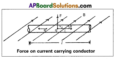
The electrons in effect move with an average velocity called drift velocity ‘Vd‘. The direction of conventional current will be opposite to the direction of drift velocity.
Let us assume that the current flows through the conductor from left ‘B’ in the plane of the paper makes an angle ‘θ’ with the direction of current ‘i’ as shown in fig.
If F’ is the force acting on the charge ‘q’ in B
∴ F’ = q Vd B sin θ
If ‘n’ represents number of moving electrons per unit volume (∵ n = \(\frac{N}{V}\))
∴ Current i = nq Vd A
If ‘N’ is the number of electrons in the length ‘L’
N = nlA
Total force on conductor F = F.N
(∵ N = nV = n × A × l) = (q Vd B sin θ) (nlA)
= (nqVdA) (lB sin θ)
F = ilB sin θ
Case (i) : If θ = 0°, FMin = 0
Case (ii) : If θ = 90°, FMax = Bil
Expression for the force between two Parallel conductors carrying conductors:
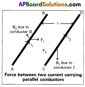
Consider two straight parallel conductors ‘AB and ‘CD’ carrying currents ‘i1‘ and ‘i2‘ and which are separated by a distance ‘r’ as shown in fig.
If B1 and B2 are magnetic inductions produced by the current carrying conductors AB and CD.
Magnetic induction B1 at a distance ‘r’ from the conductor ‘AB’ can
be written as B1 = \(\frac{\mu_0 \mathrm{i}_1}{2 \pi \mathrm{r}}\)
If ‘F’ is force acting on ‘CD’ due to magnetic induction ‘B1‘ then
FCD = i2lB1
Where l = length of the conductor
FCD = i2l(\(\frac{\mu_0 \mathrm{i}_1}{2 \pi \mathrm{r}}\)) = \(\frac{\mu_0 i_1 i_2}{2 \pi r}\) ……… (1)
The direction of the force can be determined by using Flemings left hand rule.
Similarly we can find the force acting on the conductor AB due to magnetic induction B2.
FAB = i1lB2
∴ FAB = i1l(\(\frac{\mu_0 \mathrm{i}_2}{2 \pi \mathrm{r}}\)) …………. (2) [∵ B2 = \(\frac{\mu_0 \mathrm{i}_2}{2 \pi \mathrm{r}}\) ]
From the equations (1) and (2) FAB = FCD = \(\frac{\mu_0 \mathrm{i}_1 \mathrm{i}_2}{2 \pi \mathrm{r}}\)
∴ Force between’two parallel, straight conductors carrying
currents
F = \(\frac{\mu_0 \mathrm{i}_1 \mathrm{i}_2}{2 \pi \mathrm{r}}\)
Force per unit length \(\frac{\mathrm{F}}{l}=\frac{\mu_0 \mathrm{i}_1 \mathrm{i}_2}{2 \pi \mathrm{r}}\)
![]()
Question 21.
What is a rectifier ? Explain the working of half wave and full wave rectifiers with diagrams.
Answer:
Rectifier : It is a circuit which converts ac into d.c. A p-n junction diode is used as a rectifier
Half-wave rectifier:

- A half wave rectifier can be constructed with a single diode. The ac input signal is fed to the primary coil of a transformer. The output signal is taken across the load resistance RL.
- During positive half cycle, the diode is forward biased and current flows through the diode.
- During negative half cycle, diode is reverse biased and no current flows through the load resistance.
- This means current flows through the diode only during positive half cycles and negative half cycles are blocked. Hence in the output we get only positive half cycles.
- Rectifier efficiency is defined as the ratio of output dc power to the input ac power.
η = \(\frac{\mathrm{P}_{\mathrm{dc}}}{\mathrm{P}_{\mathrm{ac}}}=\frac{0.406 \mathrm{R}_{\mathrm{L}}}{\mathrm{r}_{\mathrm{f}}+\mathrm{R}_{\mathrm{L}}}\)
Where rf = Forward resistance of a diode; RL = Load resistance
The maximum efficiency of half wave rectifier is 40.6%.
Full wave rectifier: The process of converting an alternating current into a direcf current is called rectification.
The device used for this purpose is called rectifier.
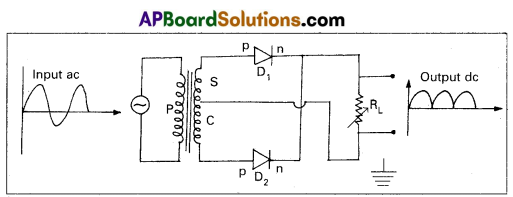
- A full wave rectifier can be constructed with the help of two diodes D1 and D2.
- The secondary transformer is centre tapped at C and its ends are connected to the p regions of two diodes D1 & D2.
- The output voltage is measured across the load resistance RL.
- During positive half cycles of ac, the diode D1 is forward biased and current flows through the load resistance RL. At this time D2 will be reverse biased and will be in switch off position.
- During negative half cycles of ac, the diode D2 is forward biased and the current flows through RL. At this time D1 will be reverse biased and will be in switch off position.
- Hence positive output is obtained for all the input ac signals.
- The efficiency of a rectifier is defined as the ratio between the output dc power to the input ac power.
η = \(\frac{\mathrm{P}_{\mathrm{dc}}}{\mathrm{P}_{\mathrm{ac}}}=\frac{0.812 \mathrm{R}_{\mathrm{L}}}{\mathrm{r}_{\mathrm{f}}+\mathrm{R}_{\mathrm{L}}}\)
The maximum efficiency of a full wave rectifier is 81.2%.