Andhra Pradesh BIEAP AP Inter 2nd Year Physics Study Material 6th Lesson Current Electricity Textbook Questions and Answers.
AP Inter 2nd Year Physics Study Material 6th Lesson Current Electricity
Very Short Answer Questions
Question 1.
Define mean free path of electron in a conductor.
Answer:
The average distance transversed by an electron during successive collisions in a conductor is called mean free path of electron in a conductor.
Question 2.
State Ohm’s law and write its mathematical form.
Answer:
At constant temperature, the strength of the current (I) in a conductor is directly proportional to the potential difference (V) between its ends.
∴ I ∝ V ⇒ I = \(\frac{\mathrm{V}}{\mathrm{R}}\) ⇒ V = IR (Mathematical form)
where R is constant, it is called the resistance of the conductor.
![]()
Question 3.
Define resistivity or specific resistance.
Answer:
Resistivity or specific resistance (ρ) : The resistance of a conductor of unit length and unit area of cross-section is called resistivity.
If l = 1, A = 1 ⇒ ρ = \(\frac{\mathrm{R} \times 1}{1}\) = ρ ⇒ R
Question 4.
Define temperature coefficient of resistance.
Answer:
Temperature coefficient of resistance (α) : The ratio of the change in resistance per 1°C rise in temperature to the resistance at 0°C is called the temperature coefficient of resistance.
α = \(\frac{R_t-R_0}{R_0 t}\)
Question 5.
Under what conditions is the current through the mixed grouping of cells maximum ?
Answer:
The current through the mixed grouping of cells maximum, when
- Effective emf of all the cells is high.
- The value of external resistance is equal to the total internal resistance of all the cells.
Question 6.
If a wire is stretched to double its original length without loss of mass, how will the resistivity of the wire be influenced ?
Answer:
Resistivity of the wire remains unchanged as it does not change with change in dimensions of a material without change in its temperature.
Question 7.
Why is manganin used for making standard resistors ?
Answer:
Due to high resistivity and low temperature coefficient of resistance, manganin wire (Cu – 84% + Mn – 12% + Ni – 4%) is used in the preparation of standard resistances.
Question 8.
The sequence of bands marked on a carbon resistor are: Red, Red, Red, Silver. What is its resistance and tolerance ?
Answer:
The resistance of a carbon resistor marked with Red, Red, Red = 22 × 102Ω = 2.2kΩ = 2200Ω
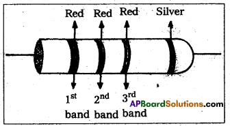
[∵ Sequence number for Red = 2 and multiplication factor = 102]
The tolerance of carbon resistor = ± 10%
Question 9.
Write the color code of a carbon resistor of resistance 23 kilo ohms.
Answer:
Color code of a carbon resistor of 23 Kilo Ohms (= 23 × 103Ω) are Red, Orange, Orange
[∵ Sequence number 2 for Red, 3 for orange, multiplication factor 103 for orange]
![]()
Question 10.
If the voltage V applied across a conductor is increased to 2V, how will the drift velocity of the electrons change ?
Answer:
The drift velocity, Vd = \(\frac{\mathrm{eE}}{\mathrm{m}}\) \(\tau^{\prime}\) = \(\frac{\mathrm{eV}}{\mathrm{mL}} \tau\)
\(\frac{\mathrm{V}_{\mathrm{d}_1}}{\mathrm{~V}_{\mathrm{d}_2}}\) = \(\frac{v_1}{v_2}\)
Here V1 = V, V2 = 2V
\(\frac{\mathbf{V}_{\mathrm{d}_1}}{\mathrm{~V}_{\mathrm{d}_2}}\) = \(\frac{V}{2 V}\)
∴ \(\mathrm{V}_{\mathrm{d}_2}\) = \(2 \mathrm{~V}_{\mathrm{d}_1}\)
∴ Drift velocity is increased by twice.
Question 11.
Two wires of equal length, of copper and, manganin, have the same resistance. Which wire is thicker ?
Answer:
R = \(\frac{\rho \mathrm{A}}{l}\) ⇒ A = \(\frac{\mathrm{R} l}{\rho}\)
Since ρcu < pmanganin, copper wire is thicker than manganin wire.
Question 12.
Why are household appliances connected in parallel ?
Answer:
In parallel, the voltage (V) across each appliance is same. The current (I) through them depends upon the power (P) of the appliance. The higher power appliance draws more current and lower power appliance draws less current.
(∵ P = VI or I ∝ P)
Question 13.
The electron drift speed in metals is small (~ms-1) and the charge of the electron is also very small (~10-19C), but we can still obtain a large amount of current in a metal. Why ?
Answer:
Current through a metal, I = n A eVd.
A is the area of cross-section of the metal. The electron drift speed, Vd (~10-5, ms-1) is small. The charge of electron, e (~1.6 × 10⁻¹⁹C) is also very small. But we can still obtain a large amount of current in a metal due to presence of large number of free electrons (n) is a conductor (~ 1029 m-3).
Short Answer Questions
Question 1.
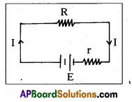
A battery of emf 10V and internal resistance 3Ω is connected to a resistor R.
- If the current in the circuit is 0.5 A. Calculate the value of R.
- What is the terminal voltage of the battery when the circuit is closed.
Answer:
Given, E = 10V, r = 3Ω, I = 0.5A, R = ?, V = ?
- E = I(R + r) or R + r = \(\frac{E}{I}\) = \(\frac{10}{0.5}\) =20Ω ⇒ R = 20 – 3 = 17Ω
- Terminal voltage, V = IR = 0.5 × 17 = 8.5Ω
![]()
Question 2.
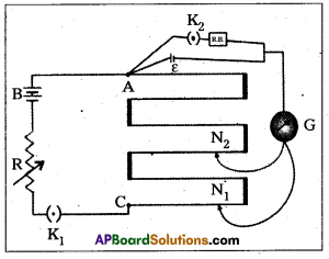
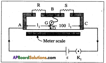
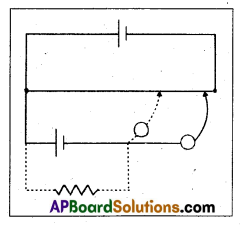
Draw a circuit diagram showing how a potentiometer may be used to find Internal resistance of a cell and establish a formula for It.
Answer:
Measurement of internal resistance (r) with potentiometer:
- Potentiometer to measure internal resistance (r) of a cell (ε) is shown in diagram.
- The cell (emf ε) whose internal resistance (r) is to be determined is connected across a resistance box (RB) through a key K2.
- With key K2 open, balance is obtained at length
l1 (AN1). Then ε = ϕl1 —– (1) - When key K2 is closed, the cell sends a current (I) through the resistance box (R.B).
- If V is the terminal potential difference of the cell and balance is obtained at length l2 (AN2). Then V = ϕl2 —– (2)
- \(\frac{(1)}{(2)}\) ⇒ \(\frac{\varepsilon}{\mathrm{V}}\) = \(\frac{l_1}{l_2}\) —- (3)
- But ε = I(r + R) and V = IR. This gives
\(\frac{\varepsilon}{\mathrm{V}}\) = \(\frac{(\mathrm{r}+\mathrm{R})}{\mathrm{R}}\)
\(\frac{I_1}{I_2}\) = \(\left(\frac{r}{R}+1\right)\) [∵ from (3)]
∴ r = R\(\left(\frac{l_1}{l_2}-1\right)\)
Question 3.
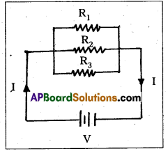
Derive an expression for the effective resistance when three resistors are connected in
(i) series
(ii) parallel. (T.S. Mar. ’19)
Answer:
Effective resistance when three resistors are connected:
(i) In series:
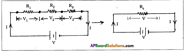
- Three resistors R1, R2 and R3 are connected in series as shown in fig. V1, V2, V3 are the potential differences across R1, R2 and R3. I is the current flowing through them.
- Applying Ohm’s law to R1, R2 and R3, Then V1 = IR1, V2 = IR2, V3 = IR3
- In series, V = V1 + V2 + V3
IRS = IR1 + IR2 + IR3 [∵ V = IRS]
∴ RS = R1 + R2 + R3
ii) In parallel:
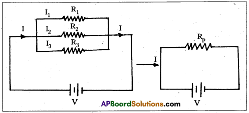
- Three resistors, R1, R2 and R3 are connected in parallel as shown in fig. Potential differences across each resistor is V. I1, I2, I3 are the currents flowing through them.
- Applying Ohmes law to R1, R2 and R3, then
V = I1R1 = I2R2 = I3R3
⇒ I1 = \(\frac{\mathrm{V}}{\mathrm{R}_1}\), I2 = \(\frac{\mathrm{V}}{\mathrm{R}_2}\), I3 = \(\frac{\mathrm{V}}{\mathrm{R}_3}\) - In parallel, I = I1 + I2 + I3
⇒ \(\frac{\mathrm{V}}{\mathrm{R}_{\mathrm{p}}}\) = \(\frac{\mathrm{V}}{\mathrm{R}_1}\) + \(\frac{\mathrm{V}}{\mathrm{R}_2}\) + \(\frac{\mathrm{V}}{\mathrm{R}_3}\) [∵ I = \(\frac{V}{R_p}\)]
∴ \(\frac{1}{\mathrm{R}_{\mathrm{p}}}\) = \(\frac{1}{R_1}\) + \(\frac{1}{R_2}\) + \(\frac{1}{R_3}\)
Question 4.
‘m’ cells each of emf E and internal resistance ‘r’ are connected in parallel. What is the total emf and internal resistance ? Under what conditions is the current drawn from mixed grouping of cells a maximum ?
Answer:
Cells in parallel:
- When ‘m’ identical cells each of emf ‘ε’ and internal resistance r are connected to the external resistor of resistance R as shown in fig., then the cells are connected in parallel.
- As the cells are connected in parallel, their equivalent internal resistance rp is given by
\(\frac{1}{\mathrm{r}_{\mathrm{p}}}\) = \(\frac{1}{\mathrm{r}}\) + \(\frac{1}{\mathrm{r}}\) + ….. upto m terms = \(\frac{\mathrm{m}}{\mathrm{r}}\)
∴ rp = \(\frac{\mathrm{r}}{\mathrm{m}}\)
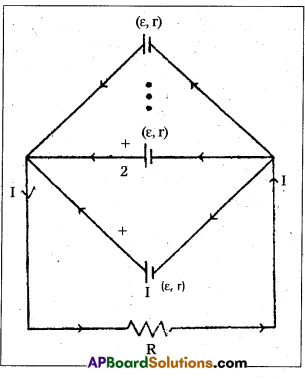
- As R and rp are in series, so total resistance in the circuit = R + \(\frac{\mathrm{r}}{\mathrm{m}}\).
- In parallel combination of identical cells, the effective emf in the circuit is equal to the emf due to a single cell, because in this combination, only the size of the electrodes increases but not emf.
- Therefore, current in the resistance R is given by I = \(\frac{\varepsilon}{\mathrm{R}+\frac{\mathrm{r}}{\mathrm{m}}}\) = \(\frac{\mathrm{m} \varepsilon}{\mathrm{m} R+\mathrm{r}}\)
- When the external resistance is negligible is comparison to the internal resistance (R<<r), the current drawn from mixed grouping of cells a maximum.
![]()
Question 5.
Define electric resistance and write it’s SI unit. How does the resistance of a conductor vary if
(a) Conductor is stretched to 4 times of it’s length
(b) Temperature of a conductor is increased.
Answer:
Electric resistance (R) : The resistance offered by a flow of electrons in a conductor is called electric resistance.
S.l unit of resistance is ohm (Ω).
The resistance of a conductor
R = \(\frac{\rho l}{\mathrm{~A}}\) = \(\frac{\rho l^2}{\mathrm{~V}}\) ⇒ R ∝ l2
a) in first case, R1 = R, l1 = l
b) In second case, l2 = 4l, R2 =?
\(\frac{R_2}{R_1}\) = \(\frac{l_2^2}{l_1^2}\) ⇒ \(\frac{R_2}{R}\) = \(\left(\frac{4l}{l_4}\right)^2\) ∴ R2 = 16R
b) Variation of Resistance with temperature is given by Rt = R0 (1 + α t)
If temperature increases, resistance also increases.
Question 6.
When the resistance connected In series with a cell is halved, the current is equal to or slightly less or slightly greater than double. Why?
Answer:
‘When he resistance R is connected to cell of emf, ε in series, the current is given by
I = \(\frac{\varepsilon}{\mathrm{R}+\mathrm{r}}\)
where r is internal resistance of cell.
When the resistance is halved \(\left(\frac{\mathrm{R}}{2}\right)\), the current flows through the circuit is I’ = \(\frac{\varepsilon}{\frac{R}{2}+r}\)
- If r is negligible comparison with \(\frac{\mathrm{R}}{2}\), I1 = \(\frac{2 \varepsilon}{R}\)
∴ I1 = 2 I [∵ \(\frac{\varepsilon}{R}\) also equal to 1] - If r < < \(\frac{\mathrm{R}}{2}\), the current I1 is slightly greater than 2.
- If r is just slightly greater than R, the current (I1) is slightly less than 2.
Question 7.
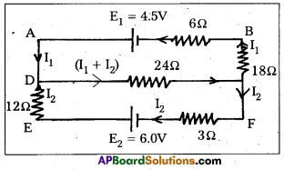
Two cells of emfs 4.5V and 6.0V and infernal resistance 6Ω and 3Ω respectively have their negative terminals joined by a wire of 18Ω and positive terminals by a wire of 12Ω resistance. A third resistance wire of 24Ω connects middle points of these wires. Using Kirchhoffs laws, find the potential difference at the ends of this third wire.
Answer:
- Let the currents through the various arms, of the network be as shown in fig:
- Applying KVL to closed mesh ABCDA, we have
4.5 – 6I1 – 18I1 – 24 (I1 + I2) = 0
⇒ 48I1 + 24I2 = 4.5 —–> (i) - For a closed mesh CDEFC, we have
– 24(I1 + I2) – 12I2 + 6 – 3I2 = 0
24I1 + 39I2 = 6 —–> (ii)
- (ii) × 2 – (i) ⇒
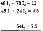
∴ I2 = \(\frac{7.5}{54}\) = 0.139 A —–> (iii)
Substituting (iii) in (i), we get
48I1 + 78 × 0.139 = 12
48I1 = 12 – 10.84 = 1.158
I1 = \(\frac{1.158}{48}\) = 0.024 A - Potential difference across third wire = (I1 + I2) × 24 = 0.163 × 24 = 3.912 Volt.
Question 8.
Three resistors each of resistance 10 ohm are connected, in turn, to obtain
(i) minimum resistance
(ii) maximum resistance. Compute
(a) The effective resistance in each case
(b) The ratio of minimum to maximum resistance so obtained.
Answer:
Given, Resistance of each resistor R = 10Ω, no. of resistors, n = 3
i) If three resistors are connected in parallel, we get minimum resistance.
∴ Minimum resistance Rmin = Rp = \(\frac{\mathrm{R}}{\mathrm{n}}\) = \(\frac{10}{3} \Omega\) = 3.33Ω
ii) If three resistors are connected in series, we get maximum resistance.
∴ Maximum resistance Rmax = Rs = n R = 3 × 10 = 30Ω
a) The effective resistance to get minimum resistance,
Reff = \(\frac{\mathrm{R}}{\mathrm{n}}\) = \(\frac{10}{3}\) = 3.33Ω (In parallel)
The effective resistance to get maximum resistance
Reff = n R = 3 × 10 = 30Ω (In series)
b) \(\frac{R_{\min }}{R_{\max }}\) = \(\frac{\left(\frac{10}{3}\right)}{(3 \times 10)}\) = \(\frac{10}{90}\) ∴ \(\frac{\mathrm{R}_{\min }}{\mathrm{R}_{\max }}\) = \(\frac{1}{9}\)
Question 9.
State Kirchhoffs law for an elêctrical network. Using these laws deduce the condition for balance in a Wheatstone bridge. (Ã.P. Mar. 19, ‘16 & Mar. 14)
Answer:
1) Kirchhoff s first law (Junction rule or KCL) : The algebraic sum of the currents at any junction is zero. ∴ ΣI = 0
(or)
The sum of the currents flowing towards a junction is equal to the sum of currents away from the junction.
2) Kirchhoffs second law (Loop rule or KVL): The algebraic sum of potential around any closed loop is zero.
∴ Σ(IR) + ΣE = 0
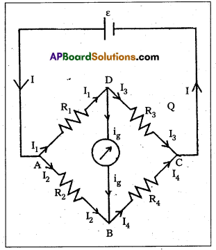
Wheatstone bridge : Wheatstone’s bridge circuit consists of four resistances R1, R2, R3 and R4 are connected to form a closed path. A cell of emf e is connected between the point A and C and a galvanometer is connected between the points B and D as shown in fig. The current through the various branches are indicated in the figure. The current through the galvanometer is Ig and the resistance of the galvanometer is G.
Applying Kirchhoffs first law at the junction D, I1 – I3 – Ig = 0 —— (1)
at the junction B, I2 + Ig – I4 = 0 —— (2)
Applying Kirchhoffs second law to the closed path ADBA,
-I1R1 + I2R2 = 0
or
⇒ I1R1 + IgG = I2R2 —– (3)
applying kirchhoffs second law to the closed path DCBD,
-I3R3 + I4R4 + IgG = 0
⇒ I3R3 – IgG = I4R4 —– (4)
When the galvanometer shows zero deflection the points D and B are at the same potential. So Ig = 0.
Substituting this value in (1), (2), (3) and (4).
I1 = I3 ——- (5)
I2 = I4 —— (6)
I1R1 = I2R2 —– (7)
I3R3 = I4R4 —– (8)
Dividing (7) by (8)
\(\frac{\mathrm{I}_1 \mathrm{R}_1}{\mathrm{I}_3 \mathrm{R}_3}\) = \(\frac{I_2 R_2}{I_4 R_4}\) ⇒ \(\frac{R_1}{R_3}\) = \(\frac{R_2}{R_1}\) [∵ I1 = I3 & I2 = I4]
∴ Wheatstone’s Bridge principle : R4 = R3 × \(\frac{\mathrm{R}_2}{\mathrm{R}_1}\)
![]()
Question 10.
State the working principle of potentiometer. Explain with the help of circuit diagram how the emf of two primary cells are compared by using the potentiometer. (T.S. Mar. 19 & A.P. Mar. 16)
Answer:
Working principle of potentiometer : The potential difference across a length of the potentiometer wire is directly proportional to its length (or) when a steady current is passed through a uniform wire, potential drop per unit length or potential gradient is constant,
i.e. ε ∝ l ⇒ ε = ϕl where ϕ is potential gradient.
Comparing the emf of two cells ε1 and ε2 :
- To compare the emf of two cells of emf E1 and E2 with potentiometer is shown in diagram.
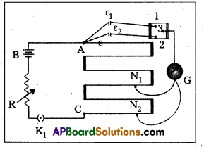
- The points marked 1, 2, 3 form a two way key.
- Consider first a position of the key where 1 and 3 are connected so that the galvanometer is connected to ε1.
- The Jockey is moved along the wire till at a point N1 at a distance l1 from A, there is no deflection in the galvanometer. Then ε1 ∝ l1 ⇒ ε1 = ϕl1 —– (1)
- Similarly, if another emf ε2 is balanced against
l2 (AN2) then ε2 ∝ l2 ⇒ ε2 = ϕl2 —— (2) - \(\frac{(1)}{(2)}\) ⇒ \(\frac{\varepsilon_1}{\varepsilon_2}\) = \(\frac{l_1}{l_2}\)
Question 11.
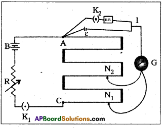
State the working principle of potentiometer explain with the help of circuit diagram how the potentiometer is used to determine the internal resistance of the given primary cell. (A.P. & T.S. Mar. ’15)
Answer:
Working principle of potentiometer : The potential difference across a length of the potentiometer wire is directly proportional to its length (or) when a steady current is passed through a uniform wire, potential drop per unit length or potential gradient is constant.
i.e. E ∝ l ⇒ e = ϕl
where ϕ is potential gradient.
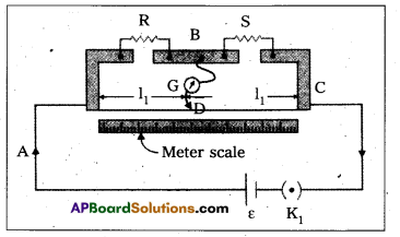
Measurement of internal resistance (r) with potentiometer:
- Potentiometer to measure internal resistance (r) of a cell (ε) is shown in diagram.
- The cell (emf ε) whose internal resistance (r) is to be determined is connected across a resistance box (R.B) through a key K2.
- With key K2 open, balance is obtained at length l1(AN1). Then ε = ϕl1 ——-> (1)
- When key K2 is closed, the cell sends a current (T) through the resistance box (R.B).
- If V is the terminal potential difference of the cell and balance is obtained at length l2 (AN2).
Then V = ϕl2 ——> (2) - \(\frac{(1)}{(2)}\) ⇒ \(\frac{\varepsilon}{\mathrm{V}}\) = \(\frac{l_1}{l_2}\) —– (3)
- But ε = I (r + R) and V = IR. This gives
\(\frac{\varepsilon}{V}\) = \(\frac{(\mathrm{r}+\mathrm{R})}{\mathrm{R}}\)
\(\frac{l_1}{l_2}\) = \(\left(\frac{r}{R}+1\right)\) [∵ from (3)]
∴ r = \(\mathrm{R}\left(\frac{l_1}{l_2}-1\right)\)
Question 12.
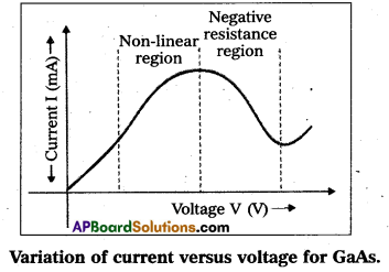
Show the variation of current versus voltage graph for GaAs and mark the
(i) Non-linear region
(ii) Negative resistance region.
Answer:
The relation between V and I is not unique. That is, there is more than one value of V for the same current I. material exhibiting such behaviour is GaAs (i.e., a light emitting diode).
Question 13.
A student has two wires of iron and copper of equal length and diameter. He first joins two wires in series and passes an electric current through the combination which increases gradually. After that he joins two wires in parallel and repeats the process of passing current. Which wire will glow first in each case ?
Answer:
1) In series combination, there will be same current through Iron and as well as copper wire. Since the rate of heat production, P = I2 R or P ∝ R (for the given value of I). The resistance of Iron wire is more than that of copper for the given length and diameter. Hence in Iron wire, the rate of heat production increases gradually. In series combination Iron will glow first.
2) In parallel combination of Iron and copper wire, there will be same P.D (V) across them.
Since the rate of heat production, P = \(\frac{\mathrm{V}^2}{\mathrm{R}}\) or P ∝ \(\frac{1}{R}\) (for the given value of V). The resistance of Iron is more than that of copper for the given length and diameter. Hence in copper wire, the rate of heat production is more.
In parallel combination copper will glow first.
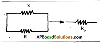
Question 14.
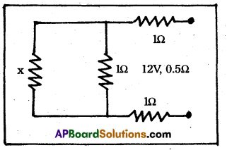
Three identical resistors are connected in parallel and total resistance of the circuit is R/3. Find the value of each resistance.
Answer:
Given three resistances are identical.
Hence R1 = R2 = R3 = x (say)
Total resistance in parallel, Rp = \(\frac{\mathrm{R}}{3}\)
If three identical resistances are connected in parallel, then
\(\frac{1}{R_p}\) = \(\frac{1}{\mathrm{R}_1}\) + \(\frac{1}{\mathrm{R}_2}\) + \(\frac{1}{\mathrm{R}_3}\)
\(\frac{1}{\left(\frac{\mathrm{R}}{3}\right)}\) = \(\frac{1}{x}\) + \(\frac{1}{x}\) + \(\frac{1}{x}\) ⇒ \(\frac{3}{\mathrm{R}}\) = \(\frac{1+1+1}{\mathbf{x}}\)
∴ x = R.
Long Answer Questions
Question 1.
Under what condition is the heat produced in an electric circuit
a) directly proportional
b) inversely proportional to the resistance of the circuit ?
Compute the ratio of the total quantity of heat produced in the two cases.
Answer:
Expression of heat produced by electric current:
Consider a conductor AB of resistance R.
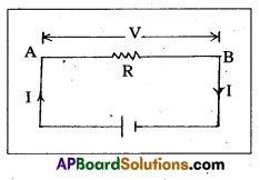
Let V = P.D applied across the ends of AB.
I = current flowing through AB.
t = time for which the current is flowing.
∴ Total charge flowing from A to B in time t is q = It. By definition of P.D, work done is carrying unit charge from A to B = V
Total work done in carrying a charge q from A to B is
W = V × q = V It = I2 Rt
(∵ V = IR)
This work done is called electric work done. If this electric work done appears as heat, then amount of heat produced (H) is given by H = W = I2 Rt Joule.
This is a statement of Joule’s law of heating.
a) If same current flows through an electric circuit, heat is developed.
i.e., H ∝ R.
b) If same P.D applied across the the electric circuit heat is developed.
i.e., H2 ∝ \(\frac{1}{\mathrm{R}}\).
c) The ratio of H1 and H2 is given by
\(\frac{\mathrm{H}_1}{\mathrm{H}_2}\) = \(\frac{\mathrm{R}}{\frac{1}{\mathrm{R}}}\)
∴ \(\frac{\mathrm{H}_1}{\mathrm{H}_2}\) = R2
Question 2.
Two metallic wires A and B are connected in parallel. Wire A has length L and radius r, wire B has a length 2L and radius 2r. Compute the ratio of the total resistance of the parallel combination and resistance of wire A.
Answer:
1) For metal Wire ‘A’
Length = L
Radius = r
Area = πr2
Resistance, RA = \(\frac{\rho_{\mathrm{A}} \mathrm{L}}{\pi \mathrm{r}^2}\) —– (i)
Where ρA is specific resistance.
For metal Wire ‘B’
Length = 2L
Radius = 2r
Area = π(2r)2 = 4πr2
Resistance, RB = \(\frac{\rho_{\mathrm{B}}(2 \mathrm{~L})}{4 \pi \mathrm{r}^2}\) = \(\frac{\rho_{\mathrm{B}} \mathrm{L}}{2 \pi \mathrm{r}^2}\) —– (ii)
Where ρB is specific resistance.
2) Total resistance of wire A and wire B in parallel combination is given by
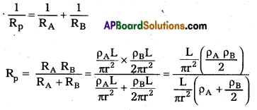
3)
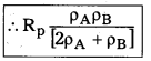
4) The ratio of the total resistance parallel combination to resistance of wire A, is given by
5)
∴ \(\frac{R_p}{R_A}\) = \(\frac{\rho_{\mathrm{B}} \pi \mathrm{r}^2}{\mathrm{~L}\left(2 \rho_{\mathrm{A}}+\rho_{\mathrm{B}}\right)}\)
Question 3.
In a house three bulbs of 100W each are lighted for 4 hours daily and six tube lights of 20W each are lighted for 5 hours daily and a refrigerator of 400W is worked for 10 hours daily for a month of 30 days. Calculate the electricity bill if the cost of one unit is Rs. 4.00.
Answer:
No. of bulbs in a house, N = 3
Rated power on each bulb, P = 100 W
Time of lighted t = 4H
Energy consumption of 3 bulbs per day = \(\frac{\mathrm{Npt}}{1000}\) KWH
Energy consumption of 3 bulbs for 30 days = \(\frac{30 \mathrm{~N} \mathrm{Pt}}{1000}\) KWH
EB = \(\frac{30 \times 3 \times 100 \times 4}{1000}\) = 36KWH
Similarly, Energy consumption of 6 tube lights for 30 days, ET = \(\frac{30 \times 6 \times 20 \times 5}{1000}\) KWH = 18 KWH.
And similarly, Energy consumption of one Refrigerator for 30 days,
ER = \(\frac{30 \times 400 \times 10}{1000}\)KWH = 120 KWH
∴ The total energy consumption, E = EB + ET + ER = (36 + 18 + 120) KWH
∴ E = 174 KWH = 174 units [∵ 1KWH = 1 unit]
Cost of 1 unit = Rs. 4.00/-
Cost of 174 units = No. of units × cost of 1 unit
= 174 × 4 = Rs. 696/-
∴ Electricity bill for one month of that house = Rs. 696/-
![]()
Question 4.
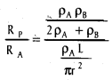
Three resistors of 4 ohms, 6 ohms and 12 ohms are connected in parallel. The combination of above resistors is connected in series to a resistance of 2 ohms and then to a battery of 6 volts. Draw a circuit diagram and calculate.
a) Current in main circuit.
b) Current flowing through each of the resistors in parallel.
c) p.d and the power used by the 2 ohm resistor.
Answer:
Circuit diagram for the given data is
a) Effective resistance when R1, R2 and R3 are connected in parallel is given by
\(\frac{1}{R_p}\) = \(\frac{1}{R_1}\) + \(\frac{1}{R_2}\) + \(\frac{1}{R_3}\) ⇒ \(\frac{1}{R_p}\) = \(\frac{1}{4}\) + \(\frac{1}{6}\) + \(\frac{1}{12}\)
⇒ \(\frac{1}{\mathrm{R}_{\mathrm{p}}}\) = \(\frac{3+2+1}{12}\) = \(\frac{6}{12}\) = \(\frac{1}{12}\)
∴ Rp = 2Ω
Total resistance in the circuit R = Rp + R4 = 2 + 2 = 4Ω
∴ Current in mam circuit I = \(\frac{\mathrm{V}}{\mathrm{R}}\) = \(\frac{6}{4}\) = 1.5A
b) Current flowing through R1, I1 = \(\frac{I R_P}{R_1}\) = \(\frac{1.5 \times 2}{4}\) = 0.75A
Current flowing through R2, I2 = \(\frac{\mathrm{IR}_{\mathrm{P}}}{\mathrm{R}_2}\) = \(\frac{1.5 \times 2}{6}\) = 0.5A
Current flowing through R3, I3 = \(\frac{\mathrm{IR}_{\mathrm{P}}}{\mathrm{R}_3}\) = \(\frac{1.5 \times 2}{12}\) = 0.25A
c) RD across 2Ω resistor (i.e., R4), V4 = IR4 = 1.5 × 2 = 3 Volt.
Power used by 2Ω resistor, P = V4I = 3 × 1.5 = 4.5 W.
Question 5.
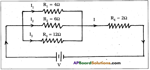
Two lamps, one rated 100 Ω at 220 V and the other 60W at 220 V are connected in parallel to a 220 volt supply. What current is drawn from the supply line?
Answer:
Data for
Since R1 and R2 are connected in parallel effective resistance
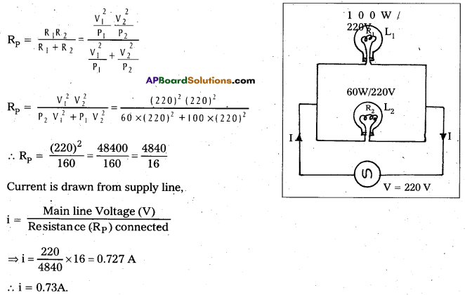
Question 6.
Estimate the average drift speed of conduction electrons in a copper wire of cross – sectional area 3.0 × 10⁻⁷ m2 carrying a current of 5 A. Assume that each copper atom contributes roughly one conduction electron. The density of copper is 9.0 × 10³ kg/m3 and its atomic mass is 63.5 u.
Answer:
Given, Cross-sectional area of copper wire, A = 3 × 10⁻⁷m2
carrying current of copper, I = 5A
Charge of electron, e = 1.6 × 10⁻¹⁹C
Density of conduction electrons = No. of atoms per cubic meter,
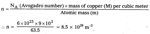
∴ Average drift speed of conduction electrons.
Vd = \(\frac{\mathrm{I}}{\mathrm{neA}}\) = \(\frac{5}{8.5 \times 10^{28} \times 1.6 \times 10^{-19} \times 3 \times 10^{-7}}\)
⇒ Vd = \(\frac{5}{8.5 \times 1.6 \times 3 \times 10^2}\) = 0.1225 × 10⁻²m/s
∴ Vd = 1.225 mm/s
Question 7.
Compare the drift speed obtained above with
i) Thermal speed of copper atoms at ordinary temperatures.
ii) Speed of propagation of electric field along the conductor which causes the drift motion.
Answer:
i) At a temperature T, the thermal speed of a copper atom of mass M is obtained from
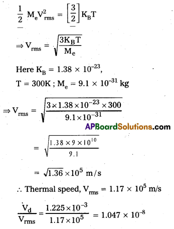
∴ drift speed of electron (Vd) = 1.047 × 10-8
= 10-8 times of thermal speed at ordinary temperature.
ii) The electric field travels along conductór with speed of EMW
C = 3 × 10⁸ m/s
Vd = 1.225 × 10⁻³m/s
\(\frac{\mathrm{V}_{\mathrm{d}}}{\mathrm{C}}\) = \(\frac{1.225 \times 10^{-3}}{3 \times 10^8}\)
Vd = 0.408 × 10⁻¹¹ C
∴ Drift speed is, in compansion of C, extremely smaller by a factor of 10-11.
Problems
Question 1.
A 10Ω thick wire is stretched so that its length becomes three times. Assuming that there Is no change in its density on stretching, calculate the resistance of the stretched wire.
Solution:
Given R1 = 10Ω,
l1 = 1
l2 = 3l, R2 ?
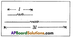
R1 = \(\frac{\rho}{\mathrm{V}} l_1^2\)
R2 = \(\frac{\rho}{\mathrm{V}} l_2^2\)
R3 = \(\left(\frac{l_2}{l_1}\right)^2\) ⇒ \(\frac{\mathrm{R}_2}{10}\) = \(\left(\frac{3 l}{l}\right)^2\)
∴ R2 = 10 × 9 = 90Ω.
Question 2.
A wire of resistance 4R is bent in the form of a circle. What is the effective resistance between the ends of the diameter? (A.P. Mar. ’19 & T.S. Mar. ’16, Mar. ’14)
Solution:
Resistance of long wire = 4R
Hence the resistance of half wire =
\(\frac{4 R}{2}\) = 2R
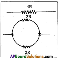
Now these two wire are connected in parallel. Hence the effective resistance between the ends of the diameter
RP = \(\frac{\mathrm{R}_1 \mathrm{R}_2}{\mathrm{R}_1+\mathrm{R}_2}\) ⇒ Rp = \(\frac{2 \mathrm{R} \times 2 \mathrm{R}}{2 \mathrm{R}+2 \mathrm{R}}\)
∴ Rp = R.
![]()
Question 3.
Find the resistivity of a conductor which carries a current of density of 2.5 × 10⁶A m-2 when an electric field of 15 Vm-1 is applied across it.
Solution:
Given current density
J = \(\frac{1}{A}\) = 2.5 × 1o6 Am-2
Applied electric field E = 15Vm-1
Resistivity of conductor,
ρ = \(\frac{E}{J}\) = \(\frac{15}{2.5 \times 10^6}\)
∴ ρ = 6 × 10⁻⁶Ωm.
Question 4.
What is the color code for a resistor of resistance 350mΩ with 5% tolerance ?
Solution:
Resistance of resistor = 350mΩ with 5% tolerance
= 350 × 10-3Ω
= 35 × 10-2Ω
First significant figure (3) indicates 1st band
Second significant figure (5) indicates 2nd band
Third significant figure (10-2) indicates 3rd band
We know that
0 1 2 3 4 5 6 7 8
B B R O Y of Great Britian has Very Good Wife wearing Gold silver Necklace
9 10-1 ← 10-2
3 indicates orange
5 indicates green
10-2 indicates Silver
5% tolerance substance is Gold.
∴ Color code of given resistor is orange, green, silver, gold.
Question 5.
You are given 8Ω resistor. What length of wire of resistivity 120 Ωm should be joined in parallel with it to get a value of 6Ω ?
Solution:
Given, Resistance of resistor R = 8Ω
Resisty of wire ρ = 120
Let l length of the resistance x is to be connected to get effective resistance,
Rp = 6Ω
Then \(\frac{1}{\mathrm{R}}\) + \(\frac{1}{x}\) = \(\frac{1}{\mathrm{R}_{\mathrm{p}}}\)
\(\frac{1}{8}\) + \(\frac{1}{x}\) = \(\frac{1}{6}\) ⇒ \(\frac{1}{x}\) = \(\frac{1}{6}\) – \(\frac{1}{8}\) = \(\frac{2}{48}\)
∴ x = 24Ω
And x l = ρ
24 l = 120
∴ l = 5m
Question 6.
Three resistors 3Ω, 6Ω and 9Ω are connected a battery. In which of them will the power dissipation be maximum if:
a) They all are connected in parallel
b) They all are connected in series ? Give reasons.
Solution:
Given R1 = 3Ω, R2 = 6Ω, R3 = 9Ω
a) Effective resistance in parallel is given by
\(\frac{1}{R_p}\) = \(\frac{1}{R_1}\) + \(\frac{1}{R_2}\) + \(\frac{1}{R_3}\) = \(\frac{1}{3}\) + \(\frac{1}{6}\) + \(\frac{1}{9}\)
\(\frac{1}{R_p}\) = \(\frac{6+3+2}{18}\)
∴ RP = \(\frac{18}{11} \Omega\)
∴ Dissipated power in parallel,
PP ∝ \(\frac{1}{\mathrm{R}_{\mathrm{P}}}\) ⇒ PP ∝ \(\frac{1}{\left(\frac{18}{11}\right)}\) ∴ PP ∝ \(\frac{11}{18}\) —– (1)
b) Effective resistance in series is given by Rs = R1 + R2 + R3 = 3 + 6 + 9 = 18Ω
∴ Dissipated power in series,
PS ∝ RS ⇒ PS ∝ 18 —- (2)
From equations (1) and (2) power dissipation is maximum in series and minimum in parallel.
Reasons:
- In series connection, P ∝ R and V ∝ R. Hence dissipated power (P) and potential difference (V) is more because current is same across each resistor.
- In parallel connection, P ∝ \(\frac{1}{R}\) and I ∝ \(\frac{1}{R}\). Hence dissipated power (P) and potential difference (V) is less because voltage is same across each resistor.
Question 7.
A silver wire has a resistance of 2.1Ω at 27.5°C and a resistance of 2.7Ω at 100°C. Determine the temperature coeff. of resistivity of silver.
Solution:
For silver wire, R1 = 2.1Ω, t1 = 27.5°C
R2 = 2.7Ω, t2 = 100°C, α = ?
α = \(\frac{R_2-R_1}{R_1 t_2-R_2 t_1}\) = \(\frac{2.7-2.1}{2.1 \times 100-2.7 \times 27.5}\)
= \(\frac{0.6}{210-74.25}\) = \(\frac{0.6}{135.75}\)
∴ Temperature coefficient of resistivity
∝ = 0.443 × 10⁻²/°C
Question 8.
If the length of a wire conductor is doubled by stretching it while keeping the potential difference constant, by what factor will the drift speed of the electrons change ?
Solution:
Taking l1 = l,
l2 = 2l
Since Vd ∝ l, \(\frac{\mathrm{v}_{\mathrm{d}_2}}{\mathrm{~V}_{\mathrm{d}_1}}\) = \(\frac{l_2}{l_1}\)
\(\frac{\mathrm{V}_{\mathrm{d}_2}}{\mathrm{~V}_{\mathrm{d}_1}}\) = \(\frac{2 l}{l}\)
∴ \(\mathrm{V}_{\mathrm{d}_2}\) = \(2 \mathrm{~V}_{\mathrm{d}_1}\)
∴ Drift speed of electrons changes by a factor 2.
Question 9.
Two 120V light bulbs, one of 25W and’ another of 200W are connected in series. One bulb burnt out almost instantaneously. Which one was burnt and why ?
Solution:
Given, For first bulb,
P1 = 25W,
V1 = 120V
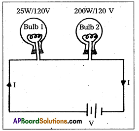
Resistance of first bulb R1 = \(\frac{\mathrm{v}_1^2}{\mathrm{P}_1}\)
R1 = \(\frac{(120)^2}{25}\) —– (1)
For second bulb, P2 = 200W, V2 = 120V
Resistance of second bulb,
R2 = \(\frac{(120)^2}{200}\) —— (2)
\(\frac{(1)}{(2)}\) ⇒ \(\frac{\mathrm{R}_1}{\mathrm{R}_2}\) = 8 ⇒ R1 = 8R2
As R1 > R2, 25 W bulb burnt out almost instantaneously, since two bulbs have rated at same voltage.
![]()
Question 10.
A cylindrical metallic wire is stretched to increase its length by 5%. Calculate the percentage change in resistance.
Solution:
Given, % change in length, \(\frac{\mathrm{d} l}{l}\) = 5%
Resistance of wire R = \(\frac{\rho l^2}{\mathrm{~V}}\)
% Change in Resistance of wire,
\(\frac{d R}{R}\) = 2\(\frac{\mathrm{d} l}{l}\) = 2 × 5% = 10%
Question 11.
Two wires A and B of same length and same material, have their cross sectional areas in the ratio 1:4. What would be the ratio of heat produced in these wires when the Voltage across each is constant ?
Solution:
Given lA = lB, ρA = ρB, VA = VB,
AA : AB = 1 : 4
Rate of heat produced in a wire,
H = i2R = \(\frac{\mathrm{V}^2}{\mathrm{R}^2}\) = \(\frac{V^2 A}{\rho l}\)
Since V, ρ, l are same for both wires A and B, H ∝ A (area of crossection)
For two wires A and B,
\(\frac{\mathrm{H}_{\mathrm{A}}}{\mathrm{H}_{\mathrm{B}}}\) = \(\frac{A_A}{A_B}\) = \(\frac{1}{4}\)
∴ HA : HB = 1 : 4.
Question 12.
Two bulbs whose resistances are in the ratio of 1:2 are connected in parallel to a source of constant voltage. What will be the ratio of power dissipation in these ?
Solution:
Given, R1 : R2 = 1 : 2, In parallel series
Dissipated power P = \(\frac{V^2}{R}\)
⇒ P ∝ \(\frac{\mathrm{I}}{\mathrm{R}}\) [ ∵ V = constant]
The ratio of dissipated powers in two bulbs is given by,
\(\frac{P_1}{P_2}\) = \(\frac{\mathrm{R}_2}{\mathrm{R}_1}\) = \(\frac{2}{1}\)
∴ P1 : P2 = 2 : 1
Question 13.
A potentiometer wire is 5m long and a potential difference of 6 V is maintained between its ends. Find the emf of a cell which balances against a length of 180cm of the potentiometer wire. (A.P. Mar. ’16)
Solution:
Length of potentiometer wire L = 5m
Potential difference V = 6 Volt
Potential gradient ϕ = \(\frac{\mathrm{V}}{\mathrm{L}}\) = \(\frac{6}{5}\) = 1.2 V / m
Balancing length l = 180cm
= 1.80m
Emf of the cell E = ϕl
= 1.2 × 1.8 = 2.16V
Question 14.
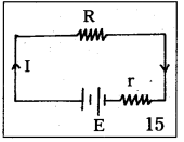
A battery of emf 2.5 V and internal resistance r is connected in series with a resistor of 45 ohm through an ammeter of resistance 1 ohm. The ammeter reads a current of 50 mA. Draw the circuit diagram and calculate the value of r.
Solution:
Circuit diagram for the given data is shown below.
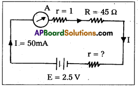
Given, E = 2.5 V; R = 4 5Ω;
rA = 1A; I = 50mA;
r = ?
E = I (R + rA + r)
2.5 = 50 × 10-3 (45 + 1 + r)
46 + r = \(\frac{2.5}{50 \times 10^{-3}}\) = \(\frac{2.5 \times 10^3}{50}\) = 50
∴ r = 50 – 46 = 4Ω.
Question 15.
Amount of charge passing through the cross section of a wire is q(t) = at2 + bt + c. Write the dimensional formula for a, b and c. If the values of a, b and c in SI unit are 6, 4, 2 respectively, find the value of current at t = 6 seconds.
Solution:
Charge passing through wire is given by q(t) = at2 + bt + c
According to principle of homogenity, Dimensional formula of q(t) = dimensional formula of at2
IT = aT2
∴ Dimensional formula a = IT-1
Dimensional formula of q(t) = Dimensional formula of bt
IT = bT
∴ Dimensional formula of b = I
Dimensional formula of q(t) = Dimensional formula of C.
IT = C
∴ Dimensonal formula of C = IT
Current, I = \(\frac{\mathrm{dq}(\mathrm{t})}{\mathrm{dt}}\) = \(\frac{\mathrm{d}}{\mathrm{dt}}\)(at2 + bt + c)
= 2at + b
Here a = 6 and b = 4
⇒ I = 12t + 4
∴ Current at t = 6 sec,
I = 12 × 6 + 4 = 76 A.
Textual Exercises
Question 1.
The storage battery of a car has an emf of 12V. If the internal resistance of the battery is 0.4Ω, what is the maximum current that can be drawn from the battery ?
Solution:
Here E = 12 V, r = 0.4Ω
Maximum Current, Imax = \(\frac{\mathrm{E}}{r}\) = \(\frac{12}{0.4}\) = 30A
Question 2.
A battery of emf 10V and internal resistance 3Ω is connected to a resistor. If the current in the circuit is 0.5 A, what is the resistance of the resistor ? What is the terminal voltage of the battery when the circuit is closed ?
Solution:
Here E = 10 V, r = 3Ω, I = 0.5 A, R = ?, V = ?
I = \(\frac{E}{(R+r)}\) or (R + r) = \(\frac{E}{I}\) = \(\frac{10}{0.5}\) = 20 or
R = 20 – r = 20 – 3 = 17Ω
Terminal voltage V = IR = 0.5 × 17 = 8.5 Ω.
Question 3.
a) Three resistors 1Ω, 2Ω, and 3Ω are combined in series. What is the total resistance of the combination ?
Solution:
Here R1 = 1Ω, R = 2 Ω, R3 = 3Ω, V = 12V
In series, total resistance RS = R1 + R2 + R3 = 1 + 2 + 3 = 6Ω.
b) If the combination is connected to a battery of emf 12 V and negligible internal resistance, obtain the potential drop across each resistor.
Solution:
Current through the circuit I = V/Rs = 12/6 = 2A
∴ Potential drop across R1 = IR1 = 2 × 1 = 2V
Potential drop across R2 = IR2 = 2 × 2 = 4V
Potential drop across R3 = IR3 = 2 × 3 = 6V
Question 4.
a) Three resistors 2Ω, 4Ω and 5Ω are combined in parallel. What is the total resistance of the combination ?
Solution:
Here R1 = 2Ω, R2 = 4Ω, R3 = 5Ω, V = 20V
In parallel combination total resistance RP is given by
\(\frac{1}{\mathrm{R}_{\mathrm{P}}}\) = \(\frac{1}{R_1}\) + \(\frac{1}{R_2}\) + \(\frac{1}{R_3}\) = \(\frac{1}{2}\) + \(\frac{1}{4}\) + \(\frac{1}{5}\) = \(\frac{10+5+4}{20}\) = \(\frac{19}{20}\) or RP = \(\frac{20}{19} \Omega\)
b) If the combination is connected to a battery of emf 20 V and negligible internal resistance, determine the current through each resistor, and the total current drawn from the battery.
Solution:
Current through R1 = \(\frac{\mathrm{V}}{\mathrm{R}_1}\) = \(\frac{20}{2}\) = 10A
Current through R2 = \(\frac{20}{4}\) = 5 A
Current through R3 = \(\frac{20}{5}\) = 4A
Total current = \(\frac{20}{\left(\frac{20}{9}\right)}\) = 19A
![]()
Question 5.
At room temperature (27.0°C) the resistance of a heating element is 100Ω. What is the temperature of the element if the resistance is found to be 117 Ω, given that the temperature coefficient of the material of the resistor is 1.70 × 10⁻⁴°C-1.
Solution:
Here R27 = 100Ω, R1 = 117Ω, t = ? α = 1.70 × 10⁻⁴°C-1
We know that
α = \(\frac{R_t-R_{27}}{R_{27}(t-27)}\) or t – 27 = Rt – R27
t = \(\frac{\mathrm{R}_1-\mathrm{R}_2}{\mathrm{R}_{27} \times \alpha}\) + 27 = \(\frac{117-100}{100 \times 1.7 \times 10^{-4}}\) + 27
= 1000 + 27 = 1027°C
Question 6.
A negligibly small current is passed through a wire of length 15m and uniform cross-section 6.0 × 10⁻⁷ m2, and its resistance is measured to be 5.0Ω. What is the resistivity of the material at the temperature of the experiment ?
Solution:
Here L = 15 m, A = 6.0 × 10⁻⁷m2, R = 5.0 Ω, ρ = ?
Question 7.
A silver wire has a resistance of 2.1 Ω at 27.5°C, and a resistance of 2.7 Ω at 100°C. Determine the temperature coefficient of resistivity of silver.
Solution:
Here R27.5 = 2.1Ω, R100 = 2.7Ω; α = ?
α = \(\frac{\mathrm{R}_{100}-\mathrm{R}_{27.5}}{\mathrm{R}_{27.5} \times(100-27.5)}\) = \(\frac{2.7-2.1}{2.1 \times(100-27.5)}\) = 0.0039°C-1
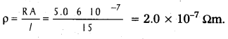
Question 8.
A heating element using nichrome connected to a 230 V supply draws an initial current of 3.2 A which settles after a few seconds to a steady value of 2.8 A. What is the steady temperature of the heating element if the room temperature is 27.0°C ? Temperature coefficient of resistance of nichrome averaged over the temperature range involved is 1.70 × 10⁻⁴°C-1.
Solution:
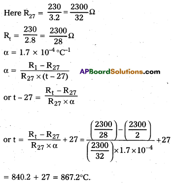
Question 9.
Determine the current in each branch of the network shown in Fig.
Solution:
The current’s through the various arms of the circuit have been shown in figure.
According to Kirchhoff’s second law;
-10 + 10 (i1 + i2) + 10i1 + 5(i1 – i3) = 0
(or) 10 = 25i + 10i – 5i3
(or) 2 = 5i1 + 2i2 – i3
(or) 2 = 5i1 + 2i2 – i3 ………. → (i)
In a closed circuit ABDA ~
10i1 + 5i3 – 5i2 = 0
(or) 2i1 + i3 – i2 = 0
(or) i2 = 2i1 + i3 …….. → (ii)
In a closed circuit BCDB
5(i1 – i3) – 10 (i2 + i3) – 5i3 = 0
(or) 5i1 – 10i2 = 20i3 =0
i1 = 2i1 + 4i3…….. → (iii)
From (ii) and (iii)
i1 = 2 (2i1 – i3) + 4i3 = 4i1 + 6i3
(or) 3i1 = -6i3
(or) i1 = -2i3
Putting this value in (ii) : i2 = 2(-2i3) i3 = -3i3
Putting values in (i)
2 = 5(-2i3) + 2(-3i3) – i3 (or) 2 = -17i3
(or) i3 = -2/17A
From (iv) i1 = -(-2/17) = -4/17A
from (v) i2 = 3(-2/17) = 6/17A
i1 + i2 = (4/17) + (6/17) = (10/17)A
i1 + i3 = (4/17) + (-2/17) = (6/17) A
i2 + i3 = (6/17) + (-2/17) = 4/17A.
Question 10.
a) In a metre bridge the balance point is found to be at 39.5 cm from the end A, when the resistor Y is of 12.5 Ω. Determine the resistance of X. Why are the connections between resistors in a Wheatstone or meter bridge made of thick copper strips ?
A meter bridge. Wire Ac is 1m long R is a resistance to be measured and S is a standard resistant
Solution:
Here l = 39.5cm, R = X = ?, S = Y = 12.5 Ω
As S = \(\frac{100-l}{l} \times \mathrm{R}\)
∴ 12.5 = \(\frac{100-39.5}{39.5} \times \mathrm{X}\)
or X = \(\frac{12.5 \times 39.5}{60.5}\) = 8.16Ω
Thick copper strips are used to minimise resistance of the connections which are not accounted in the formula.
b) Determine the balance point of the bridge above if X and Y are interchanged.
Solution:
As X and Y are interchanged therefore, l1 and l2 (i.e.) lengths are also interchanged.
Hence L = 100 – 39.5 = 60.5 cm.
c) What happens if the galvanometer and cell are interchanged at the balance point of the bridge ? Would the galvanometer show any current ?
Solution:
The galvanometer will show no current.
![]()
Question 11.
A storage battery of emf 8.0 V and internal resistance 0.5 Ω is being charged by a 120 V dc supply using a series resistor of 15.5Ω. What is the terminal voltage of the battery during charging ? What is the purpose of having a series resistor in the charging circuit ?
Solution:
Here emf of the the battery = 8.0V; voltage of d.c. supply = 120V
Internal resistance of battery r = 0.5Ω; external resistance R = 15.5Ω
Since a storage battery of emf 8V is charged with a.d.c supply of 120 V the effective emf in the circuit is given by ε = 120 – 8 = 112 V
Total resistance of the circuit = R + r = 15.5 + 0.5 = 16.0Ω
∴ Current in the circuit during charging is given by
I = \(\frac{\varepsilon}{R+r}\) = \(\frac{112}{16}\) = 7.0A
∴ Voltage across R = IR = 7.0 × 15.5 = 108.5 V
During charging the voltage of the d.c supply in a circuit must be equal to the sum of the voltage drop across R and terminal voltage of the battery
∴ 120 = 108.5 V or V= 120 – 108.5 = 11.5V
The series resistor limits the current drawn from the external source of d.c supply. In its absence the current will be dangerously high.
Question 12.
In a potentiometer arrangement, a cell of emf 1.25 V gives a balance point at 35.0 cm length of the wire. If the cell is replaced by another cell and the balance point shifts to 63.0 cm, what is the emf of the second cell ?
Solution:
Here ε1 = 1.25 V, l1 = 35.0 cm, ε2 = ?.l2 = 63.0 cm.
As \(\frac{\varepsilon_2}{\varepsilon_1}\) = \(\frac{l_2}{l_1}\) or
ε2 = \(\frac{\varepsilon_1 \times l_2}{l_1}\) = \(\frac{1.25 \times 63}{35}\) = 2.25V
Question 13.
The number density of free electrons in a copper conductor estimated in textual example 6.1 is 8.5 × 1028 m-3. How long does an electron take to drift from one end of a wire 3.0m long to its other end ? The area of cross-section of the wire is 2.0 × 10⁻⁶ m2 and it is carrying a current of 3.0 A.
Solution:
Here n = 8.5 × 1028 m-3; L = 3.0 m; A = 2.0 × 10⁻⁶ m2; I = 3.0A, t = ?
As I = n A eVd
∴ Vd = \(\frac{1}{\mathrm{nAe}}\)
Now, t = \(\frac{1}{\mathrm{v}_{\mathrm{d}}}\)
= ![]()
= \(\frac{3.08 \times 8.5 \times 10^{28} \times 2.0 \times 10^{-6} \times 1.6 \times 10^{-19}}{3.0}\)
= 2.72 × 10⁴ S
= 7hour 33 minutes.
Additional Exercises
Question 1.
The earth’s surface has a negative surface charge density of 10-9 C m-2. The potential difference of 400 kV between the top of the atmosphere and the surface results (due to the low conductivity of the lower atmosphere) in a current of only 1800 A over the entire globe. If there were no mechanism of sustaining atmospheric electric field, how much time (roughly) would be required to neutralise the earth’s surface ? (This never happens in practice because there is a mechanism to replenish electric charges, namely the continual thunderstorms and lightning in different parts of the globe). (Radius of earth = 6.37 × 10⁶m).
Solution:
Here r = 6.37 × 10⁶ m; Q = 10-9 cm2; I = 1800 A
Area of the globe A = 4πr2 = 4 × 3.14 × (6.37 × 106)2
= 509.64 × 10³C
t = \(\frac{Q}{I}\) = \(\frac{509.64 \times 10^3}{1800}\) = 283.1 S
Question 2.
a) Six lead-acid type of secondary cells each of emf 2.0 V and internal resistance 0.015Ω are joined in series to provide a supply to provide a supply to a resistance of 8.5 Ω. What are the current drawn from the supply and its terminal voltage?
Solution:
Here ε = 2.0V; n = 6; r = 0.015Ω; R = 8.5 Ω
Current I = \(\frac{n E}{R+n r}\) = \(\frac{6 \times 2.0}{8.5+6 \times 0.015}\) = 1.4A
Terminal voltage,V = IR = 1.4 × 8.5 = 11.9V.
b) A secondary cell after long use has an emf 011.9 V and a large internal resistance of 380Ω. What maximum current can be drawn from the cell ? Could the cell drive the starting motor of a car?
Solution:
Here E = 1.9 V; r = 380Ω
Imax = \(\frac{\varepsilon}{\mathrm{r}}\) = \(\frac{1.9}{380}\) = 0.005A
This amount of current cannot start a car because to start the motor, the current required is 100 A for few seconds.
Question 3.
Two wires of equal length, one of aluminium and the other of copper have the same resistance. Which of the two wires is lighter? Hence explain why aluminium wires are preferred for overhead power cables. (ρAl = 2.63 × 10⁻⁸ Ωm, ρCu = 1.72 × 10⁻⁸ Ωm, Relative density of Al = 2.7, of Cu = 8.9.)
Solution:
Given, for aluminium wire; R1 = R; l1 = l
Relative density d1 = 2.7.
For copper wire R2 = R, t2 = 1, d2 = 8.9
Let A1, A2 be the area of cross section for aluminium wire and copper wire.
We know, R1 = \(\rho_1 \frac{l_1}{\mathrm{~A}_1}\) = \(\frac{2.63 \times 10^{-8} \times l}{A_1}\)
and mass of the aluminium wire m1 = A1l1 × d1 = A1l1 × 2.7
R2 = ρ2 = \(\frac{l_2}{\mathrm{~A}_2}\) = \(\frac{1.72 \times 10^{-8} \times l}{\mathrm{~A}_2}\)
Mass of copper wire m2 = A2l2 × d2 = A2l × 8.9
Since two wires are of equal resistance R1 = R2
\(\frac{2.63 \times 10^{-8} \times 1}{\mathrm{~A}_1}\) = \(\frac{1.72 \times 10^{-8} \times l}{\mathrm{~A}_2}\) or \(\frac{\mathrm{A}_2}{\mathrm{~A}_1}\) = \(\frac{1.72}{2.63}\)
from (ii) and (iv) we have
\(\frac{\mathrm{m}_2}{\mathrm{~m}_1}\) = \(\frac{\mathrm{A}_2 l \times 8.9}{\mathrm{~A}_1 l \times 2.7}\) = \(\frac{8.9}{2.7} \times \frac{\mathrm{A}_2}{\mathrm{~A}_1}\)
= \(\frac{8.9}{2.7} \times \frac{1.72}{2.63}\) = 2.16
It shows that copper wire is 2.16 times heavier than aluminium wire since for the same value of length and resistance aluminium wire has lesser mass than copper wire, therefore aluminium wire is preferred for overhead power cables. A heavy cable may sag down owing to its own weight.
Question 4.
What conclusion can you draw from the following observations on a resistor made of alloy manganin ?
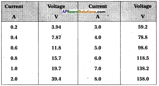
Answer:
Since the ratio of voltage and current for different readings is same so ohm’s law is valid to high accuracy. The resistivity of the alloy manganin is nearly independent of temperature.
![]()
Question 5.
Answer the following Questions.
a) A steady current flows in a metallic conductor of non-uniform cross-section. Which of these quantities is constant along the conductor: current, current density, electric field, drift speed ?
Solution:
Only current through the conductor of non-uniform area of cross section is constant as the remaining quantities vary inversly with the area of cross-section of the conductor.
b) Is Ohm’s law.universally applicable for all conducting elements ? If not, give examples of elements which do not obey Ohm’s law.
Solution:
Ohm’s law is not applicable for non-ohmic elements. For example, vaccum tubes, semi-conducting diode, liquid electrolyte etc.
c) A low voltage supply from which one needs high currents must have very low internal resistance. Why ?
Solution:
As, Imax = emf internal resistance so for maximum current internal resistance should be least.
d) A high tension (HT) supply of, say, 6 kV must have a very large internal resistance. Why ?
Solution:
A high tension supply must have a large internal resistance otherwise, if accidently the circuit is shorted, the current drawn will exceed safety limit and will cause damage to circuit.
Question 6.
Choose the correct alternative :
a) Alloys of metals usually have (greater/less) resistivity than that of their constituent metals.
b) Alloys usually have much (lower/higher) temperature coefficients of resistance than pure metals.
c) The resistivity of the alloy manganin is nearly independent of/increases rapidly with increase of temperature.
d) The resistivity of a typical insulator (e.g., amber) is greater than that of a metal by a factor of the order of (1022/1023).
Solution:
a) Greater
b) Lower
c) Nearly independent
d) 1022
Question 7.
a) Given n resistors each of resistance R, how will you combine them to get the
i) maximum,
ii) minimum effective resistance? What is the ratio of the maximum to minimum resistance ?
Solution:
For maximum effective resistance the n resistors must be connected in series.
Maximum effective resistance RS = nR
For minimum effective resistance the n resistors must be connected in parallel.
Maximum effective resistance RP = R/n
∴ \(\frac{R_S}{n p}\) = \(\frac{\mathrm{nR}}{\mathrm{R} / \mathrm{n}}\) = n2
b) Given the resistances of 1Ω, 2Ω, 3Ω, how will be combine them to get an equivalent resistance of
(i) (11/3) Ω
(ii) (11/5) Ω,
(iii) 6Ω,
(iv) (6/11)Ω?
Solution:
It is to be noted that
a) the effective resistance of parallel combination of resistors is less than the individual resistance and
b) the effective resistance of series combination of resistors is more than individual resistance.
case (i) Parallel combination of 1Ω and 2Ω is connected in series with 3Ω.
Effective resistance of 1Ω and 2Ω in parallel will be given by
RP = \(\frac{1 \times 2}{1+2}\) = \(\frac{2}{3} \Omega\)
∴ Equivalent resistance of \(\frac{2}{3} \Omega\) and 3] and 3Ω in series
= \(\frac{2}{3}\) + 3 = \(\frac{11}{3}\)Ω
Case(ii) : Parallel combination of 2Ω and 3Ω is connected in series with 1Ω.
Equivalent resistance of 2Ω and 3Ω in parallel
= \(\frac{2 \times 3}{2+3}\) = \(\frac{6}{5} \Omega\)
Equivalent resistance of \(\frac{6}{5} \Omega\) and 1Ω in series = \(\frac{6}{5}\) + 1 = \(\frac{11}{5}\)Ω
Case (iii) : All the resistances are to be connected in series now
∴ Equivalent resistance = 1 + 2 + 3 = 6Ω
Case (iv) : All the resistances are to be connected in parallel
∴ Equivalent resistance (R) is given by
\(\frac{1}{\mathrm{R}}\) = \(\frac{1}{1}\) + \(\frac{1}{2}\) + \(\frac{1}{3}\)
= \(\frac{6+3+2}{6}\) = \(\frac{11}{6}\) (Or) r = \(\frac{6}{11} \Omega\)
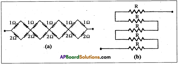
c) Determine the equivalent resistance of networks shown in Fig.
Answer:
a) The given network is a series combination of 4 equal units. Each unit has 4 resistances in which 2 resistances (1Ω each in series) are in parallel with 2 other resistances (2Ω each in series).
∴ Effective resistances of two resistances (each of 1Ω) in series = 1 + 1 = 2Ω.
Effective Resistance of two resistances (each of 2Ω) in series = 2 + 2 = 4Ω
If R is the resistance of one unit of resistances then
\(\frac{1}{\mathrm{R}_{\mathrm{P}}}\) = \(\frac{1}{2}\) + \(\frac{1}{4}\) = \(\frac{3}{4}\) or RP = \(\frac{4}{3} \Omega\)
∴ Equivalent resistance in network = 4 RP = 4 × \(\frac{4 \Omega}{3}\) = \(\frac{16 \Omega}{3}\)
b) Total resistances each of value R are connected in series. Their effective resistance = 5R.
Question 8.
Determine the current drawn from a 12 V supply with internal resistance 0.5Ω by the Infinite network shown in Fig. Each resistor has 1Ω resistance.
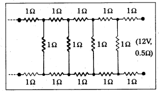
Solution:
Let x be the equivalent résistance of infinite network. Since the net work is infinite, therefore, the addition of one more unit of three resistances each of value of 1Ω across the terminals will not alter the total resistance of network i.e. it should remain x.
Therefore, the network would appear as shown in the figure and its total resistance should remain x.
There the parallel combination of x and 1Ω is in series with two resistors of 1Ω each.
The resistance of parallel combination is
\(\frac{1}{\mathbf{R}_{\mathbf{P}}}\) = \(\frac{1}{x}\) + \(\frac{1}{1}\) = \(\frac{1+x}{x}\)
Rp = \(\frac{x}{(1+x)}\)
∴ Total resistance of network will be given by
x = 1 + 1 + \(\frac{x}{x+1}\) = 2 + \(\frac{x}{x+1}\)
x(x + 1) = 2(x + 1) + x
or x2 + x = 2x + 2 + x or x2 – 2x – 2 = 0
or x = \(\frac{2 \pm \sqrt{4+8}}{2}\) = \(\frac{2 \pm \sqrt{12}}{2}\)
Total resistance of the circuit shows a full scale deflection for a current of 2.5 mA. How will you convert the meter into
= \(\frac{2 \pm 2 \sqrt{3}}{2}\) = 1 ± \(\sqrt{3}\)
The value of resistance cannot be negative, therefore the resistance of network
= 1 + \(\sqrt{3}\) = 1 + 1.73 Ω = 2.73 Ω
Total resistance of the cfrcuit = 2.73 + 0.5
= 3.23Ω
∴ Current draw I = \(\frac{12}{3.23}\) = 3.72 amp
Question 9.
Figure shows a potentiometer with a cell of 2.0’V and internal resistance 0.40 Ω maintaining a potential drop across the resistor wire AB. A standard cell which maintains a constant emf of 1.02 V (for very moderate currents upto a few mA) gives a balance point at 67.3 cm length of the wire. To ensure very low currents drawn from the standard cell, a very high resistance of 600 kΩ is put in series with it, which is shorted close to the balance point. The standard cell is then replaced by a cell of unknown emf ε and the balance point found similarly, turns out to be at 82.3 cm length of the wire.
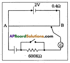
a) What is the value ε ?
Solution:
Here ε1 = 1.02 V, L1 = 67.3cm, ε2 = e = ?, L2 = 82.3 cm
Since \(\frac{\varepsilon_2}{\varepsilon_1}\) = \(\frac{\mathrm{L}_2}{\mathrm{~L}_1}\)
∴ ε = \(\frac{\mathrm{L}_2}{\mathrm{~L}_1} \times \varepsilon_1\) = \(\frac{82.3}{67.3} \times 1.02\) = 1.247V
b) What purpose does the high resistance of 600 kΩ have ?
Answer:
The purpose of using high resistance of 600k Ω is to allow very small current through the galvanometer when the movable contact is far from the balance point.
c) Is the balance point affected by this high resistance ?
Answer:
No, the balance point is not affected by the presence of this resistance.
d) Is the balance point affected by the internal resistance of the driver cell ?
Answer:
No, the balance point is not affected by the internal resistance of the driver cell.
e) Would the method work in the above situation if the driver cell of the potentiometer had an emf of 1.0V instead of 2.0V ?
Answer:
No, the method will not work as the balance point will not be obtained on the potentiometer wire if the e.m.f of the driver cell is less than the emf of the other cell.
f) Would the circuit work well for determining an extremely small emf, say of the order of a few mV (such as the typical emf of a thermo-couple) ? If not, how will you modify the circuit ?
Answer:
The circuit will not work for measuring extremely small emf because in that case the balance point will be just close to the end A. To modify the circuit we have to use a suitable high resistance in series with the cell of 2.0V This would decrease the current in the potentiometer wire. Therefore potential difference 1cm df wire will decrease. Hence extremely small emf can be measured.
![]()
Question 10.
Figure shows a potentiometer circuit for comparison of two resistances. The balance point with a standard resistor R = 10.0 Ω is found to be 58.3 cm, while that with the unknown resistance X is 68.5 cm. Determine the value of X. What might you do if you failed to find a balance point with the given cell of emf ε ?
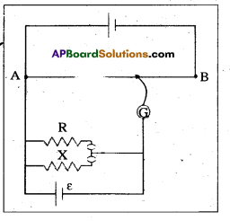
Answer:
Here L1 = 58.3cm; L2 = 68.5 cm; R = 10Ω; I X = ?. Let be the current in the potentiometer wire and ε1 and ε2 be the potential drops across R and X respectively when connected in circuit by closing respective keky. Then
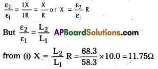
If there is no balance point with given cell of emf it means potential drop across R or X greater than the potential drop across the potentiometer wire AB. In order to obtain the balance point, the potential drops across R and X are to be reduced which is possible by reducing the current in R and X for that either suitable resistance should be put in series with R and X or a cell of smaller emf E should be used. Another possible way is to increase the potential drop across the potentiometer wire by increasing the voltage of driver cell.
Question 11.
Figure shows a 2.0 V potentiometer used for the determination of internal resistance of a 1.5 V cell. The balance point of the cell in open circuit is 76.3 cm. When a resistor of 9.5 Ω is used in the external circuit of the cell, the balance point shifts to 64.8 cm length of the potentiometer wire. Determine the internal resistance of the cell.
Solution:
Here l1 = 76.3 cm, l2 = 64.8 cm.
r = ?, R = 9.5 Ω
Now, r = \(\left(\frac{l_1-l_2}{l_2}\right) R\) = \(\left(\frac{76.3-64.8}{64.8}\right)\) 9.5 = 1.68 Ω
Textual Exercises
Question 1.
a) Estimate the average drift speed of conduction electrons in a copper wire of cross-sectional area 1.0 × 10⁻⁷ m2 carrying a current of 1.5 A. Assume that each copper atom contributes roughly one conduction electron. The density of copper is 9.0 × 10³ kg/m3, and its atomic mass is 63.5 u.
b) Compare the drift speed obtained above with,
i) thermal speeds of copper atoms at ordinary temperatures,
ii) speed of propagation of electric field along the conductor which causes the drift motion.
Solution:
a) The direction of drift velocity of conduction electrons is opposite to the electric field direction, i.e., electrons drift in the direction of increasing potential. The drift speed ud is given by Eq.
IΔt = + neA /vd/Δt
Vd = (I/neA)
Now, e = 1.6 × 10⁻¹⁹ C, A = 1.0 × 10⁻⁷ m2, I = 1.5 A. The density of conduction electrons, n is equal to the number of atoms per cubic meter (assuming one conduction electron per Cu atom as is reasonable from its valence electron count of one). A cubic metre of ‘copper has a mass of 9.0 × 10³ kg. Since 6.0 × 10²³ copper atoms have a mass of 63.5 g,
n = \(\frac{6.0 \times 10^{23}}{63.5}\) × 9.0 × 106
= 8.5 × 1028 m-3 Which gives,
\(v_{\mathrm{d}}\) = \(\frac{1.5}{8.5 \times 10^{28} \times 1.6 \times 10^{-19} \times 10 \times 10^{-7}}\)
= 1.1 × 10⁻³ m s-1 = 1.1 mm s-1
b) i) At a temperature T, the thermal speed of a copper atom of mass M is obtained from
[<(1/2) Mυ2 > = (3/2) KBT] and is thus typically of the order of \(\sqrt{\mathrm{k}_{\mathrm{B}} \mathrm{T} / \mathrm{M}}\), where KB is the Boltzmann constant. For copper at 300 K, this is about 2 × 10² m/s. This figure indicates the random vibrational speeds of copper atoms in a conductor. Note that the drift speed of electrons is much smaller, about 10-5 times the typical thermal speed at ordinary temperatures,
ii) An electric field travelling along the conductor has a speed of an electromagnetic wave, namely equal to 3.0 × 10⁸ m s-1. The drift speed is, in comparison, extremely small, smaller by a factor of 10-11.
Question 2.
a) In Textual Example 1, the electron drift speed is estimated to be only a few mm s-1 for currents in the range of a few amperes ? How then is current established almost the instant a circuit is closed ?
b) The electron drift arises due to the force experienced by electrons in the electric field inside the conductor. But force should cause acceleration. Why then do the electrons acquire a steady average drift speed ?
c) If the electron drift speed is so small, and the electron’s charge is small, how can we still obtain large amounts of current in a conductor ?
d) When electrons drift in a metal from lower to higher potential, does it mean that all the ‘free’ electrons of the metal are moving in the same direction ?
e) Are the paths of electrons straight lines between successive collisions (with the positive ions of the metal) in the i) absence of electric field,
ii) presence of electric field ?
Solution:
a) Electric field is established throughout the circuit, almost instantly (with the speed of light) causing at every point a local electron drift. Establishment of a current does not have to wait for electrons from one end of the conductor travelling to the other end. However it does take a little while for the current to reach its steady value.
b) Each ‘free’ electron does accelerate, increasing its drift speed after collision but starts to accelerate and increases its drift speed again only to suffer a collision again and so on. On the average, therefore, electrons acquire only a drift speed.
c) Simple, because the electron number density is enormous, ~1029 m-3.
d) By no means. The drift velocity is superposed over the large random velocities of electrons.
e) In the absence of electric field, the paths are straight lines, in the presence of electric field, the paths are, in general curved.
![]()
Question 3.
An electric toaster uses nichrome for its heating element. When a negligibly small current passes through it, its resistance at room temperature (27.0 °C) is found to be 75.3 Ω. When the toaster is connected to a 230 V supply, the current settles, after a few seconds, to a steady value of 2.68 A. What is the steady temperature of the nichrome element ? The temperature coefficient of resistance of nichrome averaged over the temperature range involved, is 1.70 × 10⁻⁴ °C-1.
Solution:
When the current through the element is very small, heating effects can be ignored and the temperature T1 of the element is the same as room temperature. When the toaster is connected to the supply, its initial current will be slightly higher than its steady value of 2.68 A. But due to heating effect of the current, the temperature will rise. This will cause an increase in resistance and a slight decrease in current. In a few seconds, a steady state will be reached when temperature will rise no further, and both the resistance of the element and the current drawn will achieve steady values. The resistance R2 at the steady temperature T2 is
R2 = \(\frac{230 \mathrm{~V}}{2.68 \mathrm{~A}}\) = 85.8Ω
Using the relation
R2 = R1 [1 + α(T2 – T1)]
with α = 1.70 × 10⁻⁴°C-1, we get
T2 – T1 = \(\frac{(85.8-75.3)}{(75.3) \times 1.70 \times 10^{-4}}\) = 820°C
that is, T2 = (820 + 27.0)°C = 847 °C
Question 4.
The resistance of the platinum wire of a platinum resistance thermometer at the ice point is 5 Ω and at steam point is 5.39 Ω. When the thermometer is inserted in a hot bath, the resistance of the platinum wire is 5.795 Ω. Calculate the temperature of the bath.
Solution:
R0 = 5Ω, R100 = 5.23 Ω and Rt = 5.795Ω
Now, t = \(\frac{R_t-R_0}{R_{100}-R_0} \times 100\), Rt = R0 (1 + αt)
= \(\frac{5.795-5}{5.23-5} \times 100\)
= \(\frac{0.795}{0.23} \times 100\) = 345.65°C
Question 5.
A network of resistors is connected to a 16 V battery with internal resistance of 1Ω, a shown in Fig.
a) Compute the equivalent resistance of the network.
b) Obtain the current in each resistor.
c) Obtain the voltage drops VAB, VBC and VCD.
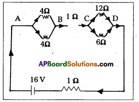
Solution:
a) The network is a simple series and parallel combination of resistors. First the two 4Ω resistors in parallel are equivalent to a resistor
= [(4 × 4)/(4 + 4)]Ω = 2Ω
In the same way, the 12Ω and 6Ω resistors in parallel are equivalent to a resistor of
[(12 × 6)/(12 + 6)]Ω = 4Ω
The equivalent resistance R of the network is obtained by combining these resistors (2Ω and 4Ω) With 1Ω in series, that is,
R = 2Ω + 4Ω + 1Ω = 7Ω
b) The total current I in the circuit is
I = \(\frac{\varepsilon}{R+r}\) = \(\frac{16 \mathrm{~V}}{(7+1) \Omega}\) = 2A
Consider the resistors between A and B. If I1 is the current in one of the 4 Ω resistors and I2 the current in the other.
I1 × 4 = I2 × 4
That is, I1 = I2, which is otherwise obvious from the symmetry of the two arms. But I1 + I2 = I = 2A. Thus,
That is, current in each 4Ω resistor is 1 A. Current in lfi resistor between B and C would be 2 A.
Now, consider the resistances between C and D. If I3 is the current in the 12Ω resistor, and I4 in the 6Ω resistor,
I3 × 12 = I4 × 6 i.e., I4 = 2I3
But, I3 + I4 = I = 2A
Thus, I3 = \(\left(\frac{2}{3}\right)\)A, I4 = \(\left(\frac{4}{3}\right) \mathrm{A}\)
That is, the current in the 12Ω resistor is (2/3)A, while the current in the 6Ω resistor is (4/3) A.
c) The voltage drop across AB is
VAB = I1 × 4 = 1 A × 4Ω = 4V
This can also be obtained by multiplying the total current between A and B by the equivalent resistance between A and B, that is,
VA = 2A × 2Ω = 4V
The voltage drop across BC is
VBC = 2A × 1Ω = 2V
Finally, the voltage drop across CD is,
VCD = 12Ω × I3 = 12Ω × \(\left(\frac{2}{3}\right) \mathrm{A}\) = 8V.
This can alternately be obtained by multiplying total current between C and D by the equivalent resistance between C and D, that is.
VCD = 2A × 4Ω = 8V
Note that the total voltage drop across AD is 4V + 2V + 8V = 14V. Thus, the terminal voltage of the battery is 14V, while its emf is 16V The loss of the voltage (= 2V) is accounted for by the internal resistance ID of the battery [2A × 1Ω = 2V].
Question 6.
A battery of 10 V and negligible internal resistance is connected across the diagonally opposite corners of a cubical network consisting of 12 resistors each of resistance 1Ω Fig. Determine the equivalent resistance of the network and the current along each edge of the cube.
Solution:
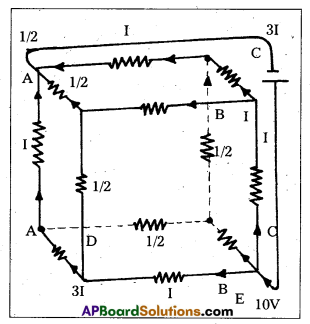
The network is not reducible to a simple series and parallel combinations of resistors. There is, however, a clear symmetry in the problem which we can exploit to obtain the equivalent resistance of the network.
The paths AA’. AD and AB are obviously symmetrically placed in the network. Thus, the current in each must be the same, say, I. Further, at the corners A’, B and D, the incoming current I must split equally into the two outgoing branches. In this manner, the current in all the 12 edges of the cube are easily written down in terms of I, using Kirchhoff’s first rule and the symmetry in the problem.
Next take a closed loop, say, ABCC’EA, and apply Kirchhoff’s second rule :
-IR – (1/2)IR – IR + ε = 0
where R is the resistance of each edge and ε the emf of battery. Thus, ε = \(\frac{5}{2}\)IR
The equivalent resistance Req of the network is Req = \(\frac{\varepsilon}{3 I}\) = \(\frac{5}{6}\)R
For R = IΩ, R,sub>eq = (5/6) Ω and for ε = 10V, the total current (=3I) in the network is 3I = 10V/(5/6) p = 12 A, i.e., I = 4 A
The current flowing in each edge can now be read off from the Fig.
Question 7.
Determine the current in each branch of the network shown in Fig.
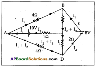
Solution:
Each branch of the network is assigned an unknown current to be determined by the application of Krichhoff’s rules. To reduce the number of unknowns at the outset, the first rule of Kirchhoff is used at every junction to assign the unknown current in each branch. We then have three unknown I1, I2 and I3 which can be found by applying the second rule of Krichhoff to three different closed loops. Kirchhoff s second rule for the closed loop ADCA gives,
10 – 4(I1 – I2) + 2 (I2 + I3 – I1) – I1 = 0
that is, 7I1 – 6I2 – 2I3 = 10 ——-> (1)
For the closed loop ABCA, we get
10 – 4I2 – 2 (I2 + I3) – I1 = 0
that is, I1 + 6I2 + 2I3 = 10 —-—> (2)
For the closed loop BCDEB, we get
5 – 2 (I2 + I3) – 2 (I2 + I3 – I1) = 0
that is, 2I1 – 4I2 – 4I3 = -5 ——–> (3)
Equations (1, 2, 3) are three simultaneous equations in three unknowns. These can be solved by the usual method to give.
I1 = 2.5A, I2 = \(\frac{5}{8}\)A, I3 = 1\(\frac{7}{8}\)A
The currents in the various branches of the network are
AB : \(\frac{5}{8}\) A, CA : 2\(\frac{1}{2}\) A, DEB : 1\(\frac{7}{8}\) A
AD = 1\(\frac{7}{8}\) A, CD : 0 A, BC : 2\(\frac{1}{2}\) A
It is easily verified that Krichhoffs second rule applied to the remaining closed loops does not provide any additional independent equation, that is, the above values of currents satisfy the second rule for every closed loop of the network. For example, the total voltage drop over the closed loop BADEB
5V + \(\left(\frac{5}{8} \times 4\right)\) – \(\left(\frac{15}{8} \times 4\right) \mathrm{V}\)
equal to zero, as required by Krichhoffs second rule.
![]()
Question 8.
The four arms of a Wheatstone bridge (Fig.) have the following resistances :
AB = 100Ω, BC = 10Ω, CD = 5Ω, and DA = 60Ω
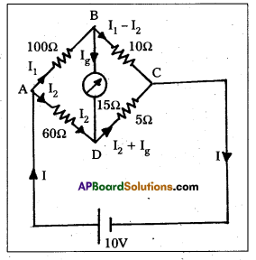
A galvanometer of 15Ω resistance is connected across BD. Calculate the current through the galvanometer when a potential difference of 10 V is maintained across AC.
Solution:
Considering the mesh BADB, we have
100I1 + 15Ig – 60I2 = 0
or 20I1 + 3Ig – 12I2 = 0 —–> (1)
Considering the mesh BCDB, we have
10(I1 – Ig) – 15Ig – 5(I2 + Ig) = 0
10I1 – 30Ig – 5I2 = 0
2I1 – 6Ig – I2 = 0 ——> (2)
Considering the mesh ADCEA,
60I2 + 5(I2 + Ig) = 10
65I2 + 5Ig = 10
13I2 + Ig = 2 —–> (3)
Multiplying equation (2) by 10 ‘
20I1 + 60Ig – 10I2 = 0
From Equations. (4) and (1) we have ——> (4)
63Ig + 2I2 = 0
I2 = 31.5Ig
Substituting the value of I2 into Equation (3) we get.
13(31.5Ig) + Ig = 2
410.5 Ig = 2
Ig = 4.87 mA.
Question 9.
In a metre bridge (Fig.), the null point is found at a distance of 36.7 cm from A. If now a resistance of 12Ω is connected in parallel with S, the null point occurs at 51.9 cm. Determine the values of R and S.
Solution:
From the first balance point, we get
\(\frac{\mathrm{R}}{\mathrm{S}}\) = \(\frac{33.7}{66.3}\) —–> (1)
After S is connected in parallel with a resistance of 12Ω, the resistance across the gap changes from S to Seq, where
Seq = \(\frac{12 \mathrm{~S}}{\mathrm{~S}+12}\) —–> (2)
and hence the new balance condition now gives
\(\frac{51.9}{48.1}\) = \(\frac{\mathrm{R}}{\mathrm{S}_{\mathrm{eq}}}\) = \(\frac{R(S+12)}{12 S}\)
Substituting the value of R/S from Equation (1), we get
\(\frac{51.9}{48.1}\) = \(\frac{\mathrm{S}+12}{12}\) . \(\frac{33.7}{66.3}\)
Which gives S = 13.5 Ω. Using the value of R/S above, we get R = 6.86 Ω.
Question 10.
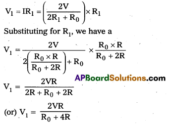
A resistance of R Ω draws current from a potentiometer. The potentiometer has a total resistance R0 Ω. (Figure) A voltage V is supplied to the potentiometer. Derive an expression for the voltage across R when the sliding contact is in the middle of the potentiometer.
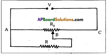
Solution:
While the slide is in the middle of, the potentiometer only half of its resistance (R0/2) will be between the points A and B. Hence, the total resistance between A and B, say, R1, will be given by the following expression.
\(\frac{1}{\mathrm{R}_1}\) = \(\frac{1}{R}\) + \(\frac{1}{\left(\mathrm{R}_0 / 2\right)}\)
R1 = \(\frac{\mathrm{R}_0 \mathrm{R}}{\mathrm{R}_0+2 \mathrm{R}}\)
The total resistance between A and C will be süm of resistance between A and B and B and C, i.e., R1 + R0/2
∴ The current flowing through the potentiometer will be
I = \(\frac{\mathrm{V}}{\mathrm{R}_1+\mathrm{R}_0 / 2}\) = \(\frac{2 \mathrm{~V}}{2 \mathrm{R}_1+\mathrm{R}_0}\)
The voltage V1 taken from the potentiometer will be the product of current I and resistance R1,