Andhra Pradesh BIEAP AP Inter 2nd Year Physics Study Material 16th Lesson Communication Systems Textbook Questions and Answers.
AP Inter 2nd Year Physics Study Material 16th Lesson Communication Systems
Very Short Answer Questions
Question 1.
What are the basic blocks of a communication system ?
Answer:
Basic blocks in communication system are
- Transmitter
- Receiver
- Channel.
Question 2.
What is “World Wide Web” (WWW) ?
Answer:
Tern Berners -Lee invented the World Wide Web.
It is an encyclopedia of knowledge accessible to every one round the clock through out the year.
![]()
Question 3.
Mention the frequency range of speech signals.
Answer:
Speech signals frequency range is 300 Hz to 3100 Hz.
Question 4.
What is sky wave propagation ?
Answer:
In the frequency range from a MHz upto about 30 MHz, long distance communication can be achieved by ionospheric reflection of radio waves back towards the earth. This mode of propagation is called sky wave propagation.
Question 5.
Mention the various parts of the ionosphere ?
Answer:
Parts of ionosphere are
- D (Part of stratosphere (65-70 km day only),
- E (Part of stratosphere (100 km day only),
- F1 (Part of mesosphere (170 km – 190 km),
- F2 (Part of thermosphere [300 km at night 250 – 400 km during day time]).
Question 6.
Define modulation. Why is it necessary ? (T.S. Mar.’19, 16, 15; A.P. Mar. 16, 15) (Mar. ’14)
Answer:
Modulation : The process of combining low frequency audio signal with high frequency carrier wave is called modulation.
Necessary : Low frequency signals cannot transmit directly. To reduce size of the antenna and to avoid mixing up of signal from different transmitters modulation is necessary.
Question 7.
Mention the basic methods of modulation. (A.P. Mar. ’19, ’16, T.S. Mar. ’15)
Answer:
The basic methods of modulation are :
- Amplitude modulation (AM)
- Frequency modulation (FM)
- Phase modulation (PM)
![]()
Question 8.
Which type of communication is employed in Mobile Phones ? (A.P. Mar. ’15)
Answer:
Space wave mode of propagation is employed in mobile phones.
Short Answer Questions
Question 1.
Draw the block diagram of a generalized communication system and explain it briefly.
Answer:
Every communication system has three essential elements :
- Transmitter
- Medium / Channel
- Receiver.
The block diagram is shown in Fig.
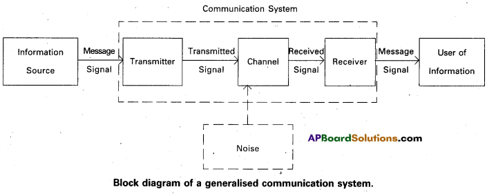
In Communication system, the transmitter and the receiver are located at two different places separate from the transmitter.
The channel is the physical medium that connects. The purpose of transmitter is to convert the message signal produced by the source of information into a form, suitable for transmission through the channel. If the output of the information source is a non-electrical signal like a voice signal, a transducer converts it to electrical form before giving it as an input to the transmitter. When a transmitted signal propagates along the channel it may get distorted due to channel imperfection. Moreover, noise adds to the transmitted signal and the receiver receives a corrupted version of the transmitted signal. The receiver has the task of operating on the received signal. It reconstructs a recognizable form of the original message signal for delivering it to the user of information.
Question 2.
What is a Ground wave ? When is it used for communication ?
Answer:
Ground Wave : To radiate signals with high efficiency, The antennas should have a size comparable to the wavelength λ of the signal (at least ~ λ/4). At longer wavelengths (i.e., at lower frequencies), the antennas have large physical size and they are located on or very near to the ground. In standard AM broadcast, ground based vertical towers are generally used as transmitting antennas. For such antennas, ground has a strong influence on the propagation of the signal. The mode of propagation is called surface wave propagation and the wave glides over the surface of the earth. A wave induces current in the ground over which it passes and it is attenuated as a result of absorption of energy by the earth. The attenuation of surface waves increases very rapidly with increase in frequency. The maximum range of coverage depends on the transmitted power and frequency (less than 2 MHz). Ground waves will propagate long distances over sea water due to its high conductivity.
Question 3.
What are Sky Waves ? Explain Sky Wave propagation, briefly.
Answer:
Sky Waves : Long distance communication between two points on the earth is achieved through reflection of electromagnetic waves by Ionosphere, Such waves are called sky waves.
This mode of propagation is used by short wave broadcast services. The Ionosphere is so called because of the presence of a large number of ions or charged particles. It extends from a height of ~ 65 Km to about 400 km above the earth’s surface.
The degree of ionisation varies with the height. The density of atmosphere decreases with height. At greater heights the solar radiation is intense but there are few molecules to be ionized. Close to the earth, the radiation intensity is low so that the ionization is again low. However at some intermediate heights, there occurs a peak of ionization density. The ionospheric layer acts as a reflector for a certain range of frequencies (3 to 30 MHz).
Electromagnetic waves of frequencies higher than 30 MHz penetrate ionosphere and escape. This phenomenon is shown in the Fig.
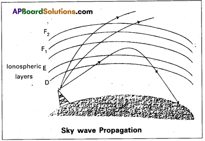
The phenomenon of bending of em waves is so that they are diverted towards the earth which is similar to Total Internal Reflection in optics.
![]()
Question 4.
What is Space Wave Communication ? Explain.
Answer:
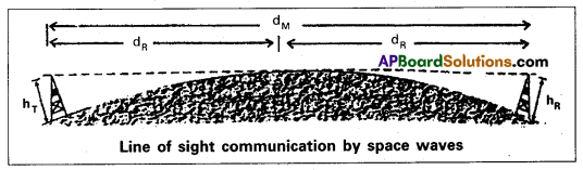
A spcae wave travels in a straight line from transmitting antenna to the receiving antenna. Space waves are used for line – of – sight (LOS) communication as well as satellite communication. At frequencies above 40 MHz, communication is essentially limited to line-of-sight paths. At these frequencies, the antennas are relatively smaller and can be placed at heights of many wavelengths above the ground. Because of line-of-sight nature of propagation, direct waves get blocked at some point by the curvature of the earth as illustrated in Fig. If the signal is to be received beyond the horizon then the receiving antenna must be high enough to intercept the line-of-sight waves.
If the transmitting antenna is at a height hT then it can be shown that the distance to the horizon dT is given as dT = \(\sqrt{\left(2 \mathrm{Rh}_{\mathrm{T}}\right)}\) where R is the radius of the earth (approximately 6400 km). Similarly if the receiving antenna is at a height hR, the distance to the horizon dR is dR = \(\sqrt{\left(2 \mathrm{Rh}_{\mathrm{R}}\right)}\). With reference to Fig. the maximum line-of sight distance dM between the two antennas having heights hT and hR above the earth is given by dM = \(\sqrt{\left(2 \mathrm{Rh}_{\mathrm{T}}\right)}\) = \(\sqrt{\left(2 \mathrm{Rh}_{\mathrm{R}}\right)}\)
Television broadcast, microwave links and satellite communication are some examples of communication systems that use space wave mode of propogation.
Question 5.
What do you understand by modulation ? Explain the need for modulation.
Answer:
The process of combining audio frequency signal with high frequency signal is called modulation.
To transmit an electronic signal in the audio frequency range (20 Hz to 20 KHz) over a long distance directly the following constraints limit the possibility :
- Size of the antenna
- Effective power radiated by the antenna
- Mixing up of signals from different transmitters.
For 20 KHz signal the height of antenna is about 4km, still a large height. This makes antenna length impractical. Even if we transmit the signal, they may combine with low frequency signals present in the atmosphere and it is impossible to distinguish the signals at the receiving end.
In order to avoid these problems a low frequency audio signal is combined with high frequency signal to translate the audio signal to high frequencies.
Question 6.
What should be the size of the antenna or aerial ? How the power radiated is related to length of the antenna and wavelength ?
Answer:
Size of antenna (or) aerial: For trasmitting a signal, we need an antenna. The size of the antenna comparable to the wavelength of the signal (at least λ/4). So that the antenna properly senses the time variation of the signal. For an e.m waves of frequency 20 kHz, the wavelength λ is 15 km. Obviously such a long antenna is not possible to construct and operate. There is a need of translating the information contained in our original low frequency base band signal into high frequencies before transmission.
Effective power radiated by an antenna : A linear antenna (length l) show that the power radiated is proportional to \(\frac{l}{\lambda^2}\). For the same antenna length, the power radiated increases with decreasing λ. i.e., increasing frequency. Hence the effective power radiated by a long wave length base band signal would be small.
Question 7.
Explain amplitude modulation.
Answer:
Amplitude modulation (AM.) : In amplitude modulation, the amplitude of carrier wave varies, but frequency and phase remains constant.
Here we can explain AM using a sinusoidal signal as a modulating signal.
Let C(t) = Ac sin ωc t represent carrier wave
m(t) = Am sin ωm t represent modulating signal.
The modulating Cm(t) can be written as
Cm(t) = (Ac + Am sin ωmt) sin ωCt
Cm(t) = Ac (1 + \(\frac{A_m}{A_c}\) sin ωmt) sin ωct —— (1)
Where ωm = 2πfm is the angular frequency of message signai
Note that the modulated signal now contains the message signal.
Cm(t) = Ac sin ωct + µ Ac sin ωmt sin ωc t —– (2)
Where µ = \(\frac{A_m}{A_c}\) = Modulation index.
To avoid distortion keep . µ ≤ 1
Cm(t) = Ac sin ωt + \(\frac{\mu A_c}{2}\) cos (ωc – ωm) t – \(\frac{\mu \mathrm{A}_{\mathrm{c}}}{2}\) cos (ωc + ωm)t —— (3)
Here (ωc – ωm) and (ωc + ωm) are lower side and upper side frequencies.
As long as the broadcast frequencies (camer wave) are sufficiently spaced out the side bands donot over lap.
Question 8.
How can an amplitude modulated wave be generated?
Answer:
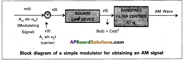
The modulated signal Am sin ωmt is added to the camer wave signal Ac sin ωct to produce the signal x(t).
x(t) = Am sin ωm t + A sin ωct is passed through a square law device produces an output.
y(t) = B x(t) + Cx2 (t)
where B and C are constant.
This signal is passed through a band pass filter. The output of band pass filter produces AM wave, In band pass filter dc and the sinusoidal frequencies ωm, 2ωm and 2ωc rejects and retains the frequency ωc, (ωc – ωm) and (ωc + ωm)
![]()
Question 9.
How can an amplitude modulated wave be detected ?
Answer:
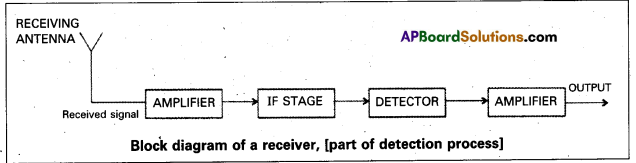
A block diagram of a typical receiver is shown in figure. Detection is the process of recovering the modulating signal from the modulated carrier wave.
We just saw that the modulated carrier wave contains the frequencies ωc and ωc ± ωm.. In order to obtain message signal m(t) of angular frequency ωm, a simple method is shown in figure.
The modulated signal is passed through a rectifier produces the output message signal. This message signal is passed through envelope detector (RC circuit).

Textual Exercises
Question 1.
Which of the following frequencies will be suitable for beyond the horizon communication using sky waves ?
(a) 10 kHz
(b) 10 MHz
(c) 1 GHz
(d) 1000 GHz
Solution:
(b) 10 kHz frequencies cannot be radiated due to large antenna size, 1GHz and 1000 GHz will be generated. So option (b) is correct.
Question 2.
Frequencies in the UHF range normally propagate by means of:
(a) Ground waves
(b) Sky waves
(c) Surface waves
(d) Space waves
Answer:
(d). The frequencies in UHF range normally propagate by means.of space waves. The high frequency space does not bend with ground but are ideal for frequency modulation.
Question 3.
Digital signals
(i) do not provide a continuous set of values
(ii) represent values are discrete steps
(iii) can utilize binary system and
(iv) can utilize decimal as well as binary systems.
Which of the above statements are true ?
(a) (i) and (ii) only
(b) (ii) and (iii) only
(c) (i), (ii) and (iii) but not (iv)
(d) All of (i), (ii), (iii) and (iv).
Answer:
(c). A digital signal is a discontinuous function of time in contrast to an analogue signal. The digital signals can be stored as digital data and cannot be transmitted along the telephone lines. Digital signal cannot utilize decimal signals.
Question 4.
Is it necessary for a transmitting antenna to be at the same height as that of the receiving antenna for line-of-sight communication ? A TV transmitting antenna is 81m tall. How much service area can it cover if the receiving antenna is at the ground level ?
Answer:
No, it is not necessary for line of sight communication, the two antennas may not be at the same height.
Given, height of antenna h = 81 m.
Radius of earth R = 6.4 × 10⁶ m.
Area = πd2; Range, d = \(\sqrt{2 \mathrm{hR}}\)
∴ Service area = π × 2πR = \(\frac{22}{7}\) × 81 × 2 × 6.4 × 106 = 3258.5 km2.
![]()
Question 5.
A carrier wave of peak voltage 12V is used to transmit a message signal. What should be the peak voltage of the modulating signal in order to have a modulation index of 75% ?
Answer:
Given, Peak voltage V0 = 12V
Modulation index μ = 75% = \(\frac{75}{100}\)
We know that Modulation index (μ)
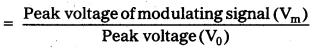
So, peak voltage of modulating signal Vm = μ × Peak voltage = \(\frac{75}{100}\) × 12 = 9V.
Question 6.
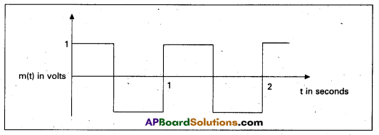
A modulating signal is a square wave, as shown in fig.
The carrier wave is given by c(t) = 2 sin (8πt) volts.
(i) Sketch the amplitude modulated waveform.
(ii) What is the modulation index ?
Answer:
Given, equation of carrier wave c(t) = 2 sin (8πt) —– (1)
(i) According to the diagram
Amplitude of modulating signal Am = 1V
Amplitude of carrier wave Ac = 2V
TM = 1s; Ωm = \(\frac{2 \pi}{T_m}\) = \(\frac{2 \pi}{1}\) = 2π rad/s —– (2)
From equation (1)
c(t) = 2 sin 8πt = Ac sin ωc
From equation (2)
so, ωc = 4ωm
Amplitude of modulated wave A = Am + Ac = 2 + 1 = 3V.
The sketch of amplitude modulated waveform is shown below.
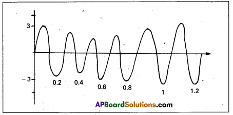
(ii) Modulation index μ = \(\frac{A_m}{A_c}\) = 0.5
Question 7.
For an amplitude modulated wave, the maximum amplitude is found to be 10V while the ‘ minimum amplitude is found to be 2V. Determine the modulation index, μ. What would be the value of m if the minimum amplitude is zero volt ?
Answer:
Given, maximum amplitude Amax = 10V
Minimum amplitude Amin = 2V
Let Ac and Am be amplitudes of carrier wave and signal wave
Amax = Ac + Am = 10 —— (1)
and Amin = Ac – Am = 2 —– (2)
Adding the equations (1) & (2) we get 2 Ac = 12; Ac = 6V; Am = 10 – 6 = 4V
Modulation index μ = \(\frac{A_m}{A_c}\) = \(\frac{4}{6}\) = \(\frac{2}{3}\).
When the minimum amplitude is zero, then i.e., Amin = 0
Ac + Am = 10 —– (3)
Ac – Am = 0 —- (4)
By solving (3) & (4) we get 2 Am = 10; Am = 5; Ac = 5
Modulation index μ = \(\frac{A_m}{A_c}\) = \(\frac{5}{5}\) = 1.
Question 8.
Due to economic reasons, only the upper sideband of an AM wave is transmitted, but at the receiving station, there is a facility for generating the carrier. Show that if a device is available which can multiply two signals, then it is possible to recover the modulating signal at the receiver station.
Answer:
Let ωc be the angular frequency of carrier waves & ωm be the angular frequency of signal waves.
Let the signal received at the receiving station be e = E1. cos (ωc + ωm) t
Let the instantaneous voltage of carrier wave ec = E0 cos ωc t is available at receiving station.
Multiplying these two signals, we get
e × ec = E1Ec cos ωct. cos (ωc + ωm) t
E = \(\frac{E_1 E_c}{2}\) 2. cos ωct. cos (ωc + ωm) t. (Let e × ec = E)
= \(\frac{\mathrm{E}_1 \mathrm{E}_{\mathrm{c}}}{2}\) [cos (ωc + ωc + ωm) t + cos (ωc + ωm – ωc) t]
∵ [2 cos A cos B = cos(A + B) + cos (A – B)]
\(\frac{E_1 E_c}{2}\) = [cos (2 (ωc + ωm)t + cos ωmt]
Now, at the receiving end as the signal passes through filter, it will pass the high frequency (2ωc + ωm)t + cos ωm) but obstruct the frequency ωm. So we can record the modulating signal \(\frac{\mathrm{E}_1 \mathrm{E}_{\mathrm{c}}}{2}\) cos ωmt which is a signal of angular frequency to ωm.